
N4A6 Product Specs

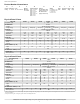
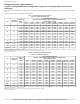


Table Of Contents
- Product Specifications
- Industry leading Features / Benefits
- Efficiency
- Reliability
- Durability
- Applications
- AHRI Ratings
- Product Number Nomenclature
- Physical Data 1-Phase
- Physical Data 3-Phase
- * Units are rated with 25 ft (7.6 m) of lineset length. See Vapor Line Sizing and Cooling Capacity Loss table when using other sizes and lengths of lineset. Note: See unit Installation Instruction for proper installation.
- { See Liquid Line Sizing For Cooling Only Systems with R-410A Refrigerant tables.
- Liquid Line Sizing and Maximum Total Equivalent Lengths{ for Cooling Only Systems with R-410A Refrigerant:
- Table 1 – Maximum Total Equivalent Length Outdoor Unit BELOW Indoor Unit
- *Maximum actual length not to exceed 200 ft (61 m)
- {Total equivalent length accounts for losses due to elbows or fitting. See the Long Line Guideline for details.
- -- = outside acceptable range
- * Maximum actual length not to exceed 200 ft (61 m)
- {Total equivalent length accounts for losses due to elbows or fitting. See the Long Line Guideline for details.
- -- = outside acceptable range
- Charging Formula:
- Long Line Applications
- Note: See Residential Piping and Long Line Guideline for details
- Applications in this area may be long line and may have height restrictions. See the Residential Piping and Long Line Guideline.
- * For tubing line sets between 80 and 200 ft. (24.38 and 60.96 m) and/or 35 ft. (10.7 m) vertical differential, refer to Residential Split-System Longline Application Guideline.
- { Additional requirement for Low-Ambient Controller (full modulation feature) MotorMasterr Control.
- } If unit equipped with ECM OD motor, both motor and fan need to be replaced per unit accessory guide to work properly. Unit will not meet AHRI rated efficiency once motor and fan are replaced to use this accessory.
- Accessory Description and Usage (Listed Alphabetically)
- Accessory Description and Usage (Listed Alphabetically) (Continued)
- Electrical Data
- * Permissible limits of the voltage range at which the unit will operate satisfactorily
- { Time-Delay fuse.
- FLA - Full Load Amps
- LRA - Locked Rotor Amps
- MCA - Minimum Circuit Amps
- RLA - Rated Load Amps
- NOTE: Control circuit is 24V on all units and requires external power source. Copper wire must be used from service disconnect to unit. All motors/compressors contain internal overload protection.
- Complies with 2010 requirements of ASHRAE Standards 90.1
- NOTE: Tested in compliance with AHRI 270–1995 (not listed with AHRI)
- * TXV must be ordered separately when indoor coil is not equipped with a TXV. TXV must be hard–shutoff type.
- IMPORTANT: When installing multiple units in an alcove, roof well, or partially enclosed area, ensure there is adequate ventilation to prevent re-circulation of discharge air.
- Detailed Cooling Capacities#
- Detailed Cooling Capacities# continued
- Detailed Cooling Capacities# continued
- Detailed Cooling Capacities# continued
- Detailed Cooling Capacities# continued
- { Total and sensible capacities are net capacities. Blower motor heat has been subtracted.
- } Sensible capacities shown are based on 80_F (27_C) entering air at the indoor coil. For sensible capacities at other than 80_F (27_C), deduct 835 Btuh (245 kW) per 1000 CFM (480 L/S) of indoor coil air for each degree below 80_F (27_C), or add 835 ...
- # Detailed cooling capacities are based on indoor and outdoor unit at the same elevation per AHRI standard 210/240-2008. If additional tubing length and/or indoor unit is located above outdoor unit, a slight variation in capacity may occur.
- ** System kw is total of indoor and outdoor unit kilowatts.
- {{ At TVA rating indoor condition (75_F edb/63_F ewb). All other indoor air temperatures are at 80_F edb.
- NOTE: When the required data falls between the published data, interpolation may be performed. Extrapolation is not an acceptable practice.
- EWB — Entering Wet Bulb
- * AHRI listing applies only to systems shown in Combination Ratings table.
- KW - Outdoor Unit Kilowatts Only.
- SDT - Saturated Temperature Leaving Compressor (°F)
- SST - Saturated Temperature Entering Compressor (°F/°C)
- TCG - Gross Cooling Capacity (1000 Btuh)
- Guide specifications GENERAL
- PRODUCTS
- system design summary
- 1. Intended for outdoor installation with free air inlet and outlet. Outdoor fan external static pressure available is less than 0.01-IN W.C.
- 2. Minimum outdoor operating air temperature without low-ambient operation accessory is 55_F (12.8_C).
- 3. Maximum outdoor operating air temperature is 125_F (51.7_C).
- 4. For reliable operation, unit should be level in all horizontal planes
- 5. For interconnecting refrigerant tube lengths greater than 80 ft (23.4 m) and/or 35 ft (10.7 m) vertical differential, consult Residential Piping and Longline Guideline and Service Manual available from equipment distributor.
- 6. If any refrigerant tubing is buried, provide a 6 in. (152.4 mm) vertical rise to the valve connections at the unit. Refrigerant tubing lengths up to 36 in. (914.4 mm) may be buried without further consideration. Do not bury refrigerant lines longe...
- 7. Use only copper wire for electric connection at unit. Aluminum and clad aluminum are not acceptable for the type of connector provided.
- 8. Do not apply capillary tube indoor coils to these units.
- 9. Factory-supplied filter drier must be installed

N4A6: Product Specifications
Manufacturer reserves the right to change, at any time, specifications and designs without notice and without obligations.
9
* Permissible limits of the voltage range at which the unit will operate satisfactorily
{ Time-Delay fuse.
FLA- Full Load Amps
LRA - Locked Rotor Amps
MCA- Minimum Circuit Amps
RLA- Rated Load Amps
NOTE:Control circuit is 24V on all units and requires external power source. Copper wire must be used from service disconnect to unit.
All motors/compressors contain internal overload protection.
Complies with 2010 requirements of ASHRAE Standards 90.1
NOTE: Tested in compliance with AHRI 270–1995 (not listed with AHRI)
* TXV must be ordered separately when indoor coil is not equipped with a TXV. TXV must be hard–shutoff type.
Electrical Data
UNIT SIZE - SERIES V/PH
OPER VOLTS* COMPR FAN
MCA
MAX FUSE{
or CKT BRK
AMPS
MAX MIN LRA RLA FLA
18GKB
208/230/1-60 253 197
47.5 9.0 0.40 11.7 20
24GKB 62.9 10.9 0.50 14.1 25
30GKB 63.0 10.9 0.50 14.1 25
36GKB 79.0 13.6 0.90 17.9 30
42GKB 109.0 16.7 0.50 21.4 35
48GKB 124.0 18.5 2.80 25.9 40
60-GKB 152.5 23.7 2.80 32.4 50
36GHB
208/230-3-60 253 187
70.0 8.10 0.90 11.0 15
48GHB 83.1 13.80 2.80 20.1 30
60GHB 110.0 15.90 2.80 22.7 35
36GLB
460-3-60 506 414
31.0 4.00 0.50 5.5 15
48GLB 41.0 6.20 1.60 9.4 15
60GLB 52.0 7.10 1.60 10.5 15
A–Weighted Sound Power (dBA) With Sound Shield
UNIT SIZE
STANDARD
RATING
TYPICAL OCTAVE BAND SPECTRUM (without tone adjustment)
125 250 500 1000 2000 4000 8000
18 75 45 53 58 62 61 55 49
24 72 48 55 59 63 59 55 49
30 73 50 54 62 66 60 57 51
36 69 48 59 57 59 56 51 40
42 72 63 57 59 61 57 55 51
48 73 55 61 64 63 60 57 48
60 73 67 68 68 71 63 55 52
A–Weighted Sound Power (dBA) Without Sound Shield
UNIT SIZE
STANDARD
RATING
TYPICAL OCTAVE BAND SPECTRUM (without tone adjustment)
125 250 500 1000 2000 4000 8000
18 75 47 56 60 64 60 54 47
24 74 48 54 60 64 59 56 50
30 74 48 55 62 67 61 57 51
36 71 49 60 59 61 59 55 47
42 74 64 57 60 61 58 56 53
48 73 55 61 64 63 60 57 48
60 74 66 67 68 72 64 60 57
METERING DEVICE
UNIT SIZE-SERIES INDOOOR REQUIRED SUBCOOLING F (°C)
18GKB
TXV*
8.0 (4.44)
24GKB 9.0 (5.00)
30GKB 11.0 (6.11)
36GKB 10.0 (5.56)
42GKB 13.0 (7.22)
48GKB 8.0 (4.44)
60GKB 10.0 (5.56)
36G(H,L)B (3-PH 10.0 (5.56)
48G(H,L)B (3-PH 8.0 (4.44)
60G(H,L)B (3-PH 9.0 (5.00)