
Installation Manual

40
Specifications are subject to change without notice.
441 01 3500 00
FIRE HAZARD
Failure to follow this warning could result in personal
injury, death, and/or property damage.
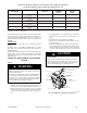
Reinstall manifold pressure tap plug in gas valve to prevent
gas leak.
!
WARNING
j. Remove thermostat jumper wire from furnace control
board.
k. Turn g as v alve ON/OFF switch to ON.
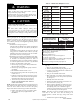
FURNACE OVERHEATING HAZARD
Failure to follow this caution may result in reduced furnace
life.
Recheck temperature rise. It must be within limits specified
on the rating plate. Recommended operation is at the
mid --point of rise range or slightly above.
CAUTION
!
l. Proceed to Step 6, “Set Blower Off Delay” before in-
stalling blower access door.
7. Set Blower Off Delay
a. Remove blower access door if installed.
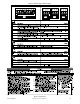
b. TurnDipswitchSW--7orSW--8ONorOFFforde-
sired blower off delay. (See Table 10 and Fig. 26 and
49.)
8. Set thermostat heat anticipator.
a. Mechanical thermostat. Set thermostat heat anticipator
to match the amp. draw of the electrical components in
the R--W/W1 circuit. Accurate amp. draw readings can
be obtained at the wires normally connected to ther-
mostat subbase terminals, R and W. The thermostat
anticipator should NOT be in the circuit while measur-
ing current.
(1.) Set SW1-- 2 switch on furnace control board to
ON.
(2.) Remove thermostat from subbase or from wall.
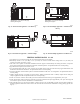
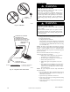
(3.) Connect an amp. meter as shown in Fig. 47.
across the R and W subbase terminals or R and
W wires at wall.
(4.) Record amp. draw across terminals when furnace
is in low heat and after blower starts.
(5.) Set heat anticipator on thermostat per thermostat
instructions and install on subbase or wall.
(6.) Turn SW1--2 switch OFF.
(7.) Install blower access door.
b. Electronic thermostat: Set cycle rate for 3 cycles per
hr.
9. Set Airflow for Air Conditioning --Single Stage and High
Stage Cooling
The ECM blower can be adjusted for a range of airflow
for Low Speed or High Speed cooling. See Table 5 --Air
Delivery -- CFM (With Filter ). Depending on the model
size, the cooling airflow can be adjusted from 1.5 to 6 tons
based on 350 CFM/ton.
The cooling airflow is adjusted by turning Setup switches
SW2--1, SW2--2 and SW2--3 either ON or OFF. Select the
required airflow from Fig. 53. Fig. 53 is based on 350
CFM per ton. For airflow at 400 CFM per ton, turn Setup
SW1--5 ON (See Table 10 and Fig. 26 and 49.)
NOTE: 5.5 ton airflow will truncate at 2200 cfm on applicable
models. For a complete explanation of cooling airflow, refer to
the section titled “Sequence of Operation.”
10. Set Airflow For Continuous Fan/Low Speed Cooling Air-
flow The ECM blower motor can be adjusted for continu-
ous fan speeds different than heating or cooling fan speed.
See T able 5 -- Air Delivery -- CFM (With Filter). Select the
required continuous fan airflow from Fig. 53.
The continuous fan speed is also the switch setting for low
speed cooling when furnace is used with a 2--speed cool-
ing unit. Adjust the Continuous Fan CFM to match the
airflow required for low speed cooling. Select the required
airflow from Fig. 51. For airflow at 400 CFM per ton, turn
Setup SW1 --5 ON (See Fig. 53.) The airflow selected for
low speed cooling will also be the airflow used for contin-
uous fan.