
Service Manual


SERVICE AND MAINTENANCE FAN COILS
496 08 8001 02 9
Specifications subject to change without notice.
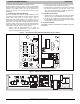
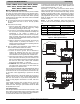
EASY SELECT CONFIGURATION TAPS
The Easy Select taps are used by installer to configure
system. The ECM 5.0 uses selected taps to modify its
operation to a pre−programmed table of airflows. Airflows are
based on system size and mode of operation and those
airflows are modified in response to other inputs such as the
need for de−humidification. (See Figure 5.)
The FVM4 Fan Coils must be configured to operate properly
with system components with which it is installed. To
successfully configure a basic system (see information printed
on circuit board located next to select pins), move the six
select wires to pins which match components used, along with
homeowner preferences.
A. Auxiliary Heat Range
The installer must select the auxiliary heat airflow approved for
application with kW size heater installed. Each select pin is
marked with a range of heaters for which airflow (also marked)
is approved. For increased comfort select the narrowest kW
range matching the heater size, for example, 0−10 for a
10−kW heater. This airflow must be greater than the minimum
CFM for electric heater application with the size system
installed for safe and continuous operation. Note that airflow
marked is the airflow which will be supplied in emergency heat
mode and heating mode on air conditioners when electric heat
is primary heating source. To ensure safe heater operation in
heat−pump heating mode, when electric heaters are
energized, the ECM 5.0 will run the higher of heat pump
airflow and electric heater airflow. The factory default selection
is largest heater range approved. (See Figure 5.)
B. AC/HP Size
The factory default setting for air conditioner or heat pump size
is largest unit meant for application with model of fan coil
purchased. The installer needs to select air conditioner or heat
pump size to ensure that airflow delivered falls within proper
range for size of unit installed in all operational modes. (See
Figure 5.)
Unpack unit and move to final location. Remove carton taking
care not to damage unit. Inspect equipment for damage prior
to installation. File claim with shipping company if shipment is
damaged or incomplete.
Locate unit rating plate which contains proper installation
information. Check rating plate to be sure unit matches job
specifications.
C. System Type
The type of system must be selected.
1. AC—air conditioner (approx. 350 CFM/ton)
2. HP−COMFORT—provides lower airflow than air
conditioner selection (approximately 315 CFM/ton) in
heating mode. In cooling mode supplies 350 CFM/ton.
3. HP−EFF—provides same airflow for heat pump heating
and cooling modes (approximately 350 CFM/ton).
The factory setting is AC. (See Figure 5.)
D. AC/HP CFM Adjust
Select low, nominal, or high airflow. The factory selection is
NOM. The adjust selections HI/LO will regulate airflow
supplied for cooling and heat pump heating modes only, +15
percent and −10 percent respectively. The adjust selection
options are provided to adjust airflow supplied to meet
individual installation needs for such things as noise, comfort,
and humidity removal. (See Figure 5.)
E. ON/OFF Delay
NOTE: ON/OFF Delay is active only in cooling and heat pump
only heating modes. In auxiliary heat mode or emergency heat
mode, the ON delay is 0 seconds and the OFF delay is fixed
and cannot be overridden.
Select desired time delay profile. Four motor−operation delay
profiles are provided to customize and enhance system
operation. (See Figure 5.) The selection options are:
1. The standard 90−seconds off delay (factory setting
0/90).
2. No delay option used for servicing unit or when a
thermostat is utilized to perform delay functions (0/0).
3. A 30−seconds on/90−
seconds off delay profile used
when it is desirable to allow system coils time to heat
up/cool down prior to airflow. This profile will minimize
cold blow in heat pump operation and could enhance
system efficiency (30/90).
4. ENH, enhanced selection provides a 30−seconds
on/150−seconds at 70 percent airflow and no off delay.
F. Continuous Fan
Select desired continuous−fan profile LO, MED, or HI. Airflow
are provided to customize and enhance the continuous fan
functions. (See Figure 5.) The possible selections are:
1. LO—provides 50 percent of Y/Y2 Cool airflow.
2. MED—provides 65 percent of Y/Y2 Cool airflow (71
percent on 5 ton model).
3. HI—provides 100 percent of Y/Y2 Cool airflow.
The factory setting is LO.
NOTE: If applied to two−speed unit, do not select continuous
fan as HI since low speed cooling will also run at HIGH airflow
and insufficient dehumidification may result.
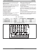
G. Easy Select Board Jumpers
J1 − This jumper must be pulled to activate dehumidification
mode. The jumper connects R to DH. With the jumper in, the
DH terminal is always energized. With the jumper pulled, the
DH terminal is de−energized. A thermostat capable of a
DEHUM feature must be used to supply the 24−V signal when
there is no call for dehumidification, and turn off the 24−V
when there is a call for dehumidfication.
J2 − This jumper activates heat staging. The jumper connects
the W1 and W2 terminals together. If either is energized, W2
airflow is delivered. With the jumper pulled, there are separate
airflows for W1 and W2.
H. Airflow Delivery
These units deliver airflow depending on the system size
selections and operating mode. The thermostat energizes a
combination of terminals on the Easy Select Board which tells
the motor what CFM to deliver. The following are typical
operating modes and the terminals that should be energized
on the Easy Select Board.
NOTE: The DH terminal on the Easy Select Board is for
dehumidification. It is de−energized on a call for
dehumidification.
I. Variable Speed Motor Logic Sequence:
The ECM motors in these fan coils are programmed to deliver
a variety of airflows. The motor goes through:
COOLING
The nominal cooling airflow for these fan coils is 350 CFM per
ton. Selecting the HI adjust tap increases the airflow to 400
CFM per ton. The LO tap decreases airflow to 315 CFM per
ton. The low adjustment is only active during normal cooling
mode. Removing the signal from the DH terminal reduces the
airflow to 80 percent of cooling airflow. Removing the G signal