
Installation Manual

4 428 01 5700 02
Specifications subject to change without notice.
Outdoor units may be connected to indoor section using accessory
tubing package or field- supplied refrigerant grade tubing of correct
size and condition. For tubing requirements between 80 - 100 ft.
(24.38 - 30.48 m), capacity and performance losses can occur .
Follow the pipe sizing recommendations in the CVH8, HVH8,
TVH8 Product data to manage these losses. This unit shall not be
installed with greater than 100 ft (30.48 m) of equivalent line
length.
Refer to Table 1 for field tubing diameters. No additional
accessories are required for line lengths between 80 - 100 ft. (24.4
- 30.5 m) on this product.
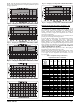
Ta ble 1 – Refrigera nt Connections and Recommended Liquid and Vapor Tube Diameters (in.)
UNIT SIZE
LIQUID VAPOR
†
Connection
Diameter
Tube
Diameter
Connection
Diameter
Max (Rated)
Diameter
Minimum
Tube Diameter
24 3/8 3/8 3/ 4 3/4 5/8
25 3/8 3/8 3/ 4 7/8 5/8
36 3/8 3/8 3/ 4 7/8 5/8
37 3/8 3/8 7/ 8 (1- 1/8) 5/8
48 3/8 3/8 7/ 8 (1- 1/8) 3/ 4
60 3/8 3/8 7/ 8 (1- 1/8) 3/ 4
{ Units are rated with 25 ft. (7.6 m) of lineset. See Product Data sheet for performance data when using different size and length line sets.
Notes:
1. Do not apply capillary tube indoor coils to these units.
Outdoor Unit Connected to Factory- Approved Indoor
Unit
Outdoor unit contains correct system refrigerant charge for
operation with factory- approved, AHRI- rated indoor units when
connected by 15 ft. (4.57 m) of field- supplied or factory- accessory
tubing, and factory- supplied filter drier. Check refrigerant charge
for maximum efficiency .
NOTE: If the indoor furnace coil width is more than the furnace
casing width, refer to the indoor coil Installation Instructions for
transition requirements.
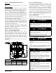
Install Liquid- Line Filter Drier Indoor
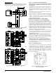
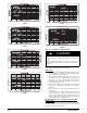
Refer to Fig. 3 and install filter drier as follows:
1. Braze 5- in. (127 mm) liquid tube to the indoor coil.
2. Wrap filter drier with damp cloth.
3. Braze filter drier to above 5 - in. (127 mm) liquid tube.
4. Connect and braze liquid refrigerant tube to the filter drier.
CAUTION
!
UNIT DAMAGE HAZARD
Failure to follow this caution may result in unit damage or
improper operation.
Installation of filter drier in liquid line is required.
A05227
Fig. 3 - Liquid- Line Filter Drier
Refrigerant Tubing connection Outdoor
Connect vapor tube to fitting on outdoor unit vapor service valves
(see T able 1).
No Installation of Adapter Tube
Although it is a heat pump this unit has a standard AC liquid
service valve. An electronic expansion valve (EXV) inside the unit
serves as the heating expansion device.
Sweat Connections
CAUTION
!
UNIT DAMAGE HAZARD
Failure to follow this caution may result in equipment
damage or improper operation.
S Use a brazing shield
S W rap service valves with wet cloth or heat sink material.
Use refrigerant grade tubing. Service valves are closed from factory
and ready for brazing. After wrapping service valve with a wet
cloth, braze sweat connections using industry accepted methods
and materials. Consult local code requirements. Refrigerant tubing
and indoor coil are now ready for leak testing. This check should
include all field and factory joints.
Evacuate Refrigerant Tubing and Indoor Coil
CAUTION
!
UNIT DAMAGE HAZARD
Failure to follow this caution may result in equipment
damage or improper operation.
Never use the system compressor as a vacuum pump.
Refrigerant tubes and indoor coil should be evacuated using the
recommended deep vacuum method of 500 microns. The alternate
triple evacuation method may be used. See Service Manual for
triple evacuation method. Always break a vacuum with dry
nitrogen prior to opening the refrigerant system for servicing.
Deep Vacuum Method
The deep vacuum method requires a vacuum pump capable of
pulling a vacuum of 500 microns and a vacuum gauge capable of
accurately measuring this vacuum depth. The deep vacuum method
is the most positive way of assuring a system is free of air and
liquid water . (See Fig. 4)