
Installation Manual


14 428 01 5700 02
Specifications subject to change without notice.
6. During the removal of the compressor fusite cap, do not re-
move the RTV sealant. Remove the harness plug, measure
the resistances, and compare to Table 5.
7. Special care will need to be taken with the replacement of
the compressor fusite cap. Make sure the two holes in the
compressor fusite terminal box are still full of RTV sealant
before the cap is reinstalled. The factory RTV can be reused
as long as none of it has been removed during the cap
removal.
8. Reinstall compressor sound blanket making sure discharge
thermistor and compressor power harness are routed as they
were from the factory
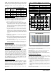
Ta ble 5 – Variable Speed Compresso r Resista nce
(winding resistance at 70_F 20_F)
WINDING
MODEL CVH8, HVH8, TVH8
24 25 36 37, 48 60
Between
terminals
1.13
OHM
.59
OHM
.59
OHM
.37
OHM
.24
OHM
Between
terminal &
ground
>1 mega OHM
UNIT DAMAGE HAZARD
Failure to follow this caution may result in equipment damage
and/or improper operation.
Do not use Meggar for measuring the winding resistance.
CAUTION
!
UNIT DAMAGE HAZARD
Failure to follow this caution may result in equipment damage
and/or improper operation.
To maintain water integrity of the compressor fusite terminal
box, the two holes in outer ring need to be full of RTV sealant.
CAUTION
!
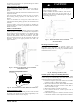
Fan Motor
If verification of proper operation is required for the fan motor
used in this unit, follow these steps:
1. Disconnect fan motor connector from control board.
2. Measure resistance between any 2 of the 3 leads present.
3. Compare measurement to values below
Fan Motor Resistance
Unit Size Resistance (Ohms)
24 21.2
25, 36, 37, 48, 60 11.1
Status Codes
Occasionally the unit may become unresponsive due to
certain combinations of previous fault codes. There may
not be anything wrong with the unit or components. The
unit may require a high voltage power cycling for at
least 2 minutes or longer to clear the condition. If the
condition persists, conduct further troubleshooting per
the service manual.
!
ATTENTION
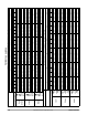
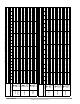
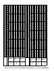
Table 6 shows the status codes flashed by the amber status light.
Most system problems can be diagnosed by reading the status code
as flashed by the amber status light on the control board.
The codes are flashed by a series of short and long flashes of the
status light. The short flashes indicate the first digit in the status
code, followed by long flashes indicating the second digit of the
error code.
The short flash is 0.25 seconds ON and the long flash is 1.0 second
ON. Time between flashes is 0.25 seconds. Time between short
flash and first long flash is 1.0 second. Time between code
repeating is 2.5 seconds with LED OFF.
Codes are easily read from Observer
®
Wall Control
EXAMPLE:
3 short flashes followed by 2 long flashes indicates a 32 code.
Table 6 shows this to be low pressure switch open.
Status Code Recall Mode
Active status codes are stored in memory even when power is
absent. The most recently flashing status code (highest priority
active) can be recalled from memory via status code recall mode
and displayed using the amber LED. The status code recall mode is
accessed by shorting (use a clip wire) the “force defrost” connector
(labeled J2 on the board) and then power ON the unit. Please make
sure the unit is turned OFF before shorting the pins. Status call
recall mode will continue as long as the “force defrost” terminals
remain shorted. The unit will not attempt to heat or cool while the
terminals remain shorted. Once the status code is read, power down
the unit and remove the short.