
Installation Manual


428 01 5700 02 13
Specifications subject to change without notice.
The thermistor comparisons are not performed during low ambient
cooling or defrost operation.
Failed Thermistor Default Operation
Factory defaults have been provided in the event of failure of
outdoor air thermistor (OAT) and/or outdoor coil thermistor
(OCT).
If the OAT sensor should fail, defrost will be initiated based on coil
temperature and time.
If the OCT sensor should fail, defrost will occur at each time
interval during heating operation, but will terminate after 2
minutes.
If there is a thermistor out- of- range error, defrost will occur at
each time interval during heating operation, but will terminate after
2 minutes.
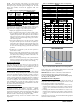
Count the number of short and long flashes to determine the
appropriate flash code. Table 6 gives possible causes and actions
related to each error.
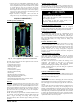
Outdoor Coil Thermistor
The outdoor coil thermistor is a 10Kohm resistor used for multiple
system operations. It provides the coil/liquid line temperature to
the heat pump board and user interface. Low ambient operation,
defrost initiation, defrost termination and assistance with OAT
temperature measurement of some of the functions. The sensor
must be securely mounted to the tube connecting the EXV and
distributor. See Fig. 26 for proper placement. See Table 4 for
proper resistances.
A14302
Fig. 25 - Outdoor Coil Thermistor (OCT) Atta chment
(On Distributor Tube)
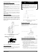
OAT Thermistor must be locked in place with
spherical nib end facing towards the front of
the control box
A11142
Fig. 26 - OAT Thermistor Location (Bottom of Control Box)
Suction Thermistor (OST)
Suction Thermistor is used for assisting in EXV control and must
be secured on the suction tube and aligned longitudinally to the
vertical surface of the tube axis (see Fig. 27).
CAUTION
!
UNIT DAMAGE HAZARD
Failure to follow this caution may result in equipment
damage or improper operation.
In order to minimize the ambient influence, make sure the
thermistor curved surface hugs the pipe surface and is
secured tight using the wire tie fished through the original
slot insulating polymer body.
A14023
Fig. 27 - Suction Thermistor (OST) Attachment
(On Suction Tube)
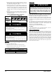
Discharge Thermistor (ODT)
Discharge Thermistor is used for protection against over
temperature of the compressor . The ODT is located on the
compressor discharge stub - out (see Fig. 28). Maximum ODT is
approximately 240 F° (116 C°).
A14024
Fig. 28 - Discharge Thermistor (ODT)
Variable Speed Compressor Winding Resistance
This compressor operates with 3- phase variable frequency PWM
variable voltage. For troubleshooting certain fault codes related to
compressor resistances, follow these steps:
1. Disconnect compressor power leads from the inverter MOC
terminals, U (YEL), V (RED), and W (BLK).
2. Measure the resistance between YEL to RED, YEL to BLK,
and RED to BLK and compare to Table 5 values. Each re-
sistance set should be equal.
3. Measure the resistance to ground for each lead.
4. If the resistances check out, reconnect power leads to
appropriate terminal.
5. If the resistances appear to be abnormal, it will be necessary
to measure the resistance at the compressor fusite terminals.