
Installation Manual


428 01 5700 02 11
Specifications subject to change without notice.
1. Connect g auges to CVH8, HVH8, TVH8 liquid and v apor
service valve ports to monitor operating pressures during
and at completion of the procedure. Attach recovery system
or vacuum pump to gauge set as needed for the service
procedure. The service valves must be open to evacuate the
unit through the line set service ports. The suction capillary
service port is a direct connection to the suction port of the
compressor and may also be used.
2. Begin evacuation or refrigerant. Allow extra time for
refrigerant recovery and establishing a thorough evacuation.
MAJOR COMPONENTS
Variable speed Control Board
A160120
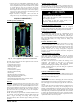
Fig. 22 - AOC (Application Operational Control) Board
The AOC board is located in the lower right hand side of inverter
tray. It’s functions include:
S Compressor speed control
S Outdoor fan motor control
S Reversing valve operation
S Defrost operation
S Crankcase heater operation
S Pressure switch monitoring
S Time Delays
S Pressure Transducer measurements
S PEV control (pressure equalizer valve)
S Temperature measurements
S EXV (Electronic Expansion Valve) operation control
S Inverter communication and control
Inverter
The inverter is located inside the control box. This is an air- cooled
device that communicates with the control board and drives the
compressor and fan motor to the demanded RPM. The inverter is
always powered with line voltage since no contactor is used. The
inverter changes the line voltage to DC volts and then recreates 3
phase sine waves that vary in frequency to drive the compressor
and fan motor at the desired RPM.
NOTE: The unit may be operated with an Observer
®
Wall Control
or a standard 2- stage HP thermostat. Observer Wall Control will
utilize 5 stages of heating and cooling, while 2- stage HP
thermostat will only allow 2 discrete stages of heating and cooling
operation.
Variable Speed Compressor
This unit contains a variable speed rotary compressor that has a
wide operating range. It operates on a variable 3 phase sine wave
provided by the inverter. This compressor can only be operated by
the specific inverter supplied with the unit.
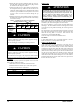
EQUIPMENT DAMAGE HAZARD
Failure to follow this caution may result in equipment damage
and/or improper operation.
Do not attempt to apply line voltage directly to the
compressor. This will destroy the compressor.
CAUTION
!
Elec tronic Expansion Valve (EXV)
This unit uses an electronic expansion valve for refrigerant
metering in the heating mode. The control board drives the EXV to
its proper position based on the operating mode and conditions.
Field control Connections
For communicating operation use the communication green
Observer p lug only. Only two wires, DX+, DX- , (GN, YL), are
required. If necessary, connect C for additional grounding (see
Fig. 6). If using standard 2- stage HP thermostat, connect discrete
inputs (R,C,Y2,Y1,O,W) for 2 - stage control in heating and
cooling modes.
Pressure Transducer (SPT)
A 5 VDC output low pressure transducer that provides a 0 - 5 VDC
data for interpretation by the control board for a 0 to 200 psig
range of pressure at the suction tube. This interpreted pressure data
is then intelligently used by the AOC control board for low
pressure cut- out, loss of charge management, compressor
protection, oil circulation management, lubrication management
and EXV control.
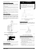
Pressure Equalizer Valve (PEV)
At the end of every compressor operation (after the 3.5 minute
Time Guard period), the equalizer valve opens for 150 seconds
plus an additional 15 seconds of protection before allowing the
compressor to start ramping up.
The PEV is located next to the suction and discharge of the
compressor. The function of this valve is to prevent the
compressor from starting with a high refrigerant pressure
differential, thus helping the reliability of the compressor.
NOTE: A hissing sound may be heard during the equalization
process. This is normal.
TROUBLESHOOTING
Systems Communication Failure
If communication is lost with the Observer Wall Control, the green
LED will go out. Check the wiring to the User Interface and the
indoor and outdoor units and power.
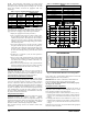
Model Plug
Each control board contains a model plug. The correct model plug
must be installed for the system to operate properly (see Table 3).
The model plug is used to identify the type and size of unit to the
control.
On new units, the model and serial numbers are inputted into the
AOC board’s memory at the factory. If a model plug is lost or
missing at initial installation, the unit will operate according to the
information input at the factory and the appropriate error code will
flash temporarily. A FAST Parts replacement AOC board contains
no model and serial information. If the factory control board fails,
the model plug must be transferred from the original board to the
replacement board for the unit to operate.