
Installation Manual

10 428 01 5700 02
Specifications subject to change without notice.
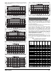
Fig. 16 - Heating Pressure Check Chart CVH8, HVH8,
TVH824
Fig. 17 - Heating Pressure Check Chart CVH8, HVH8,
TVH825
Fig. 18 - Heating Pressure Check Chart CVH8, HVH8,
TVH836
Fig. 19 - Heating Pressure Check Chart CVH8, HVH8,
TVH837
Fig. 20 - Heating Pressure Check Chart CVH8, HVH8,
TVH848
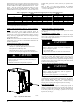
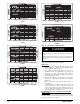
Heating Check Chart - 060
Fig. 21 - Heating Pressure Check Chart CVH8, HVH8,
TVH860
Step 13 — Pumpdown & Evacuation
CAUTION
!
ENVIRONMENTAL HAZARD
Failure to follow this caution may result in environmental
damage.
Federal regulations require that you do not vent refrigerant to
the atmosphere. Recover during system repair or final unit
disposal.
If this system requires either a Pump Down or Evacuation for any
reason, the procedures below must be followed:
Pump Down
1. Connect g auges to CVH8, HVH8, TVH8 liquid and v apor
service valve ports to monitor operating pressures during
and at completion of the procedure.
2. Force system to operate in high stage by creating a large
differential between room temperature and set point on
thermostat. Use multi- meter to verify that 24 VAC is
present between C and Y1 and Y2 terminals at outdoor unit.
3. Close the liquid service valve.
4. The unit will continue to run until high or low pressure
switches open. Close vapor service valve once compressor
shuts down.
5. Remove power from indoor and heat pump unit prior to
servicing unit.
6. A quantity of charge will remain in isolated section of
system dependent on ambient temperature and overall
system charge. This charge must be manually recovered. A
recovery system will be required to remove final quantity of
refrigerant from indoor coil and line set.
Evacuation and recovery of refrigerant from CVH8,
HVH8,
TVH8
Refrigerant recovery and evacuation can be performed but will take
more time. If EXV is not forced open the recovery and evacuation
must rely on check valve as a bypass.