
Installation Manual

26 440 01 4900 00
Specifications subject to change without notice.
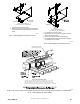
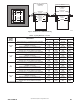
2-IN.
(51 mm)
COMBUSTION-AIR PIPE
(SEE VENTING SECTION)
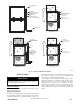
Install 12” x 22” (204 x 559 mm) sheet metal in front of and above the burner compartment area.
T
he sheet metal MUST extend above the furnace casing by 1-in. (25 mm with the door removed.
A 1-in. (25 mm) clearance minimum between top of furnace and combustible material is required.
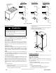
T
he entire length of furnace must be supported when furnace is used in horizontal position to
ensure proper drainage.
NOTE: FURNACE SHOWN IS A DIRECT-VENT APPLICATION. REFER TO THE VENTING SECTION FOR
ALLOWABLE VENT CONFIGURATIONS.
ROLLOUT PROTECTION REQUIRED
A150581
NOTE: Local codes may require a drain pan and condensate trap when a condensing furnace is installed over a finished ceiling.
Fig. 28 -- Suspended Furnace Installa tion
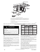
Filter Arrangement
FIRE, CARBON MONOXIDE AND POISONING
HAZARD
Failure to follow this warning could result in fire, personal
injury or death.
Never operate a furnace without a filter or filtration device
installed. Never operate a furnace with filter or filtration
device access doors removed.
!
WARNING
There are no provisions for an internal filter in these furnaces. An
external filter rack is required and is purchased separately. A field
supplied accessory air cleaner may also be used in place of the filter
rack.
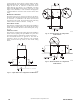
For upflow applications, the filter can be installed on either side of
the furnace, the bottom of the furnace or any combination of side
and bottom of the furnace. (See Fig. 22)
For downflow applications, the filter rack (or field supplied
accessory air cleaner) must only be connected to the bottom
opening on the furnace (See Fig. 23).
For horizontal applications, the filter rack (or field supplied
accessory air cleaner) can be connected to the bottom opening on
the furnace. For side return use in the horizontal position, refer to
Fig. 24. If both side and bottom openings are used in Fig. 24, each
opening used will require a filter.
A filter rack or any field supplied accessory air cleaner can also be
installed in the common return duct prior to entering the return air
opening in any orientation.
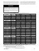
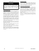
FURNACE
CASING
WIDTH
FILTER SIZE
FILT ER TYPE
SIDE
RETURN
BOTTOM
RETURN
14---3/16{
(360)
16 x 25 x 3/4
(406 x 635 x
19)
14 x 25 x 3/4
(356 x 635 x
19)
Washable*
17---1/2
(445)
16 x 25 x 3/4
(406 x 635 x
19)
16 x 25 x 3/4
(406 x 635 x
19)
Washable*
21 (533)
16 x 25 x 3/4
(406 x 635 x
19)
20 x 25 x 3/4
(508 x 635 x
19)
Washable*
24---1/2
(622)
16 x 25 x 3/4
(406 x 635 x
19)
24 x 25 x 3/4
(610 x 635 x
19)
Washable*
* Recommended to maintain air filter face velocity. See Specification Sheet
for part number.
Refer to the instructions supplied with the Filter Rack or accessory
air filter for assembly and other details.
Due to the relatively high pressure drops of 1--in (25 mm) thick
after--market filter media, it is recommended that the filtration
system be designed for at least 2 --in (51 mm) thick media.
TIPS FROM CONTRACTORS: Install a media cabinet capable
of incorporating a 4--in (102 mm) thick media filter. This allows
room for future upgrades to other IAQ devices.
Refer to the instructions supplied with Media Cabinet or accessory
air filter for assembly and other details.
See Table 7 for filter size details.
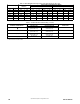
Filter and Return Duct Sizing
Pressure drop must be taken into account when sizing filters, filter
racks, IAQ devices, and associated system ductwork. See Table 5
for a comparison of Pressure Drop (initial/clean resistance to
airflow) versus Airflow for a variety of filter media types and sizes.
These are representative numbers. Consult the filter or IAQ device
manufacturers’ specification sheet for performance data for a
particular filter media or IAQ device.