
Installation Manual


428 01 5700 02 9
Specifications subject to change without notice.
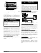
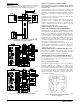
NOTE: If the line length is beyond 80ft (24.38 m) or greater than
20ft (6.10 m) vertical separation see Long line guideline for special
charging requirement.
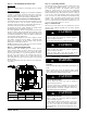
Fig. 10 - Charging in Cooling Mode CVH8, HVH8, TVH824
Fig. 11 - Charging in Cooling Mode CVH8, HVH8, TVH825
Fig. 12 - Charging in Cooling Mode CVH8, HVH8, TVH836
Fig. 13 - Charging in Cooling Mode CVH8, HVH8, TVH837
Fig. 14 - Charging in Cooling Mode CVH8, HVH8, TVH848
Fig. 15 - Charging in Cooling Mode CVH8, HVH8, TVH860
Heating Check Chart Procedure (See Fig.17 - 20)
(Communicating / Non- communicating Systems)
In heating mode, the required charging method is by weigh- in. On
new installations or complete recharge, refer to the unit 0 and
indoor fan coil / furnace coil per Table 2 for additional charge
needed. Refrigerant charge adjustment amount for adding or
removing 0.6 oz/ft (17.74 g/m) of 3/8 liquid line above or below
15ft (4.57 m) respectively.
Use the Forced Defrost mode to remove ice or frost from coil, if
present, prior to checking the heating pressures.
To use the Heating Check Chart in non - communicating systems,
operate system at Y1+Y2–high stage with a large room
temperature difference with heat pump only mode. These charts
indicate whether a correct relationship exists between system
operating pressure and air temperature entering indoor and outdoor
units. If pressure and temperature do not match on chart, system
refrigerant charge may not be correct. DO NOT USE CHART TO
ADJUST REFRIGERANT CHARGE.
NOTE: High pressure is at vapor service valve. Add 12 psig if
high pressure is taken from liquid service valve.
NOTE: When charging is necessary during heating season, char ge
must be weighed in accordance with unit rating plate,
±0.6 oz./ft
(±17.74 g/m). of 3/8- in. liquid- line above or below 15 ft (4.57
m), respectively.
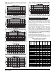
Table 2 – Required Charge (values in lbs.)
Adjustment for Indoor Coil Model
Furnace Coil
or
Fan Coil
Model
Number
24 25 36 37 48 60
EA*4X24 / / / / / /
EHD4X24 / / / / / /
EHD4X30 / / / / / /
F(V,C)M4X24 - - - - / /
EA*4X30 - / / / / /
EN(A,D)4X30 - / / / / /
ENH4X36 - - - - / /
F(V,C)M4X36 - - - - / /
EA*4X36 - - - - / /
END4X42 +.50 - - +.75 / /
EA*4X42 +.50 - - +.75 / /
EHD4X36 / - - +.75 / /
EHD4X42 / +.75 +.75 +.75 / /
EN(A,D)4X31 / +.75 +.75 +.75 / /
EN*4X48 / +.7 5 +.75 +.75 - /
EHD4X48 / +.75 +.75 +1.00 - /
EN(A,D)4X37 / / / / / /
EN(A,D)4X43 / / / / / /
EA*4X48 / / +.75 +1.00 - /
EN*4X60 / / / +1.00 - -
EHD4X60 / / / +1.00 - -
F(V,C)M4X48 / +.75 +.75 +1.00 - /
F(V,C)M4X60 / / / +1.00 +2.2 +1.00
EA*4X60 / / / / +2.2 +1.00
EN*4X61 / / / / / /
/ = Comb. n ot allowed
- = No charge adjust for ID