
Installation Manual


8 428 01 5700 02
Specifications subject to change without notice.
Outdoor Fan Motor Operation
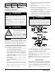
The outdoor unit control (Fig. 9) energizes outdoor fan anytime the
compressor is operating, except for defrost. The OD fan motor is
variable speed. The speed will change depending on the ambient
temperature and the cooling or heating capacity required. When the
OFM begins to start, it will rotate back and forth a couple times
slowly . It will eventually rotate full speed.
Time Delays
The unit time delays include:
S 3.5 minute time delay after last cycle, initial power up, return
from brown- out condition. To bypass this feature, momentarily
short and release Forced Defrost pins.
S At the end of every compressor ON cycle, there will be 150
seconds of PEV open period for pressure equalization followed
by 15 seconds of PEV Off period before the next compressor
ON cycle. This delay cannot be bypassed as it helps compressor
reliability.
S 15 second delay at termination of defrost before the auxiliary
heat is de- ener gized.
S See Table 6 for other delay information.
Communication and Status Function Lights
Observer
®
Wall Control, Green Communications
(COMM)Light
A green LED (COMM light) on the outdoor board (see Fig. 9)
indicates successful communication with the other system
products. The green LED will remain OFF until communication is
established. Once a valid command is received, the green LED will
turn ON continuously. If no communication is received within 2
minutes, the LED will be turned OFF until the next valid
communication. The green LED will be turned off when using a
standard 2- stage non- communicating heat pump thermostat.
Amber Status Light
Amber colored STATUS light indicates operation and error status.
See Table 6 for definitions.
S Two minute time delay to return to standby operation from last
valid communication.
Defr ost
The Observer Wall Control offers 5 possible defrost interval times:
30, 60 and 90 minutes, or AUTO. The default is AUTO.
Defrost interval times: 30, 60, and 90 minutes or AUTO are
selected by the Observer
®
Wall Control if using Wall Control. The
90 and 120 minute selection will default to 60 minutes at ambient
below 37 degrees. The 120 minute selection will default to 90
minutes at ambient above 37 degrees.
If using a non- communicating thermostat, defrost intervals are set
using dip switches on the outdoor control board (see Fig. 9), and
AUTO is not available.
AUTO defrosts adjusts the defrost interval time based on the last
defrost time as follows:
S When defrost time <5 minutes, the next defrost interval=90
minutes. (outdoor temperature above 37_F)
S When defrost time 5- 7 minutes, the next defrost interval=60
minutes.
S When defrost time >7 minutes, the next defrost interval=30
minutes.
The control board accumulates compressor run time. As the
accumulated run time approaches the selected defrost interval time,
the control board monitors the coil temperature sensor for a defrost
demand. If a defrost demand exists, a defrost cycle will be initiated
at the end of the selected time interval. A defrost demand exists
when the coil temperature is at or below 32_F(0_C) for 4 minutes
during the interval. If the coil temperature does not reach 32_F
(0_C) within the interval, the interval timer will be reset and start
over.
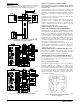
A14021
Fig. 9 - AOC Control Board
S Upon initial power up the first defrost interval is defaulted to 30
minutes. Remaining intervals are at selected times.
S Defrost is only allowed to occur below 50_F(10_C) outdoor
ambient temperature.
The defrost cycle is terminated as described below.
S When OAT is > 25_F(+3.89_C), defrost terminates if outdoor
coil temperature (OCT) > 60_F (+15.6_C). And a minimum of 2
minutes defrost length.
S When OAT ≥ 25_F(+3.89_C), defrost will terminate if OCT is
>45_F(+4.4_C) and a minimum of 2 minutes defrost length.
S Or 10 minutes has passed.
At the defrost termination, the outdoor fan will turn on 10 seconds
before the reversing valve switching.
NOTE: Compressor speed during defrost will go to defrost speed.
Step 12 — Check Charge
Charging Procedure: Force system to operate in high stage
cooling by creating a lar ge differential between room temperature
and set point on thermostat. Use multi- meter to verify that 24
VAC is present between C, Y1 /Y2 terminals at outdoor unit.
Factory charge amount is shown on unit rating plate for high stage.
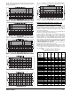
Target subcooling chart is provided on back of control box door
see Fig. 10 - 15 for example. To properly check or adjust charge,
condition must be favorable for subcooling charging. Favorable
conditions exists when outdoor temperature is between 65_F
(18_C) and 100_F(38_C), and the indoor temperature is between
70_F(21_C) and 80_F(27_C). Follow the procedure below:
Unit is factory charged for 15ft (4.57 m) of lineset. Adjust charge
by adding or removing 0.6 oz/ft (17.7 g/m) of 3/8 liquid line above
or below 15ft (4.57 m) respectively.
For standard refrigerant line lengths (80ft/24.4 m or less), allow
system to operate in cooling mode at least 25 minutes. If conditions
are favorable, check system charge by subcooling method. If any
adjustment is necessary, adjust charge slowly and allow system to
operate for 25 minutes to stabilize before declaring a properly
charged system.
If the indoor temperature is below 70°F (21.11°C), or the outdoor
temperature is not in the favorable range, adjust charge for line set
length above or below 15ft (4.57 m) and indoor fan coil /furnace
coil per Table 4. Charge level should then be appropriate for the
system to achieve rated capacity. The charge level should then be
checked at another time when the both indoor and outdoor
temperatures are in a more favorable range.