
Installation Manual


12 428 01 5700 02
Specifications subject to change without notice.
NOTE: The model plug takes priority over factory model
information input at the factory. If the model plug is removed after
initial power up, the unit will operate according to the last valid
model plug installed, and flash the appropriate fault code
temporarily.
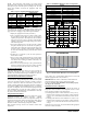
Table 3 – Factory Supplied Model Plug Information
CVH8, HVH8,
TVH8
FAST PART
NUMBER
PIN RESISTANCE
Pins 1- 4
(R1)
Pins 2- 3
(R2)
24 1184941 18K 75K
25 1188069 18K 11K
36 1184943 18K 120K
37 1188070 18K 24K
48 1184945 18K 180K
60 1184947 18K 270K
Pressure Switch Protection
The outdoor unit is equipped with high pressure switch. If the
control senses the opening of a high pressure switch (open 600+/- 5
psig, close 470+/- 10 psig @77_F), it will respond as follows:
1. Display the appropriate fault code (see Table 6).
2. After a 15 minute delay, if there is a call for cooling or heat-
ing and HPS is reset, the PEV opens for 150 seconds to
equalize system pressures. The compressor and fan will then
ramp to the next lower stage of operation until demand is
satisfied. In the next call for heating/cooling system will re-
sume normal operation.
3. If the opened switch closes at any time after the 15 minute
delay, then the PEV opens for 150 seconds to equalize sys-
tem pressures. The compressor and fan will then ramp to the
next lower stage of operation until demand is satisfied. In
the next call for heating/cooling system will resume normal
operation.
4. If HPS trips 3 consecutive cycles, the unit operation is
locked out for 4 hours.
5. In the event of a high- pressure switch trip or high- pressure
lockout, check the refrigerant charge, outdoor fan operation,
and outdoor coil (in cooling) for airflow restrictions, or in-
door airflow in heating.
6. In the event of a low- pressure trip or low- pressure lockout,
check the refrigerant charge and indoor airflow (cooling)
and outdoor fan operation and outdoor coil in heating.
Brown- Out Protection
If the line voltage is less than 187V for at least 4 seconds, the
Compressor and OD fan goes to 0 rpm. Compressor and fan
operation are not allowed until voltage is a minimum of 190V. The
control will flash the appropriate fault code (see Table 6).
230V Line (Power Disconnect) Detection
The control board senses the presence of absence of 230V through
inverter feedback. Voltage should present at all times when system
is in service regardless if system is running or standby. If there is
no 230V at the inverter when the indoor unit is powered with a
cooling or heating demand, the appropriate fault code is displayed
on the Observer
®
Wall Control (communicating only – see Table 6).
If system is configured with conventional heat pump thermostat
(non- communicating), no fault code will be displayed on AOC
board, nor will any status LEDs be lit. Use multimeter to check for
the presence of 230V in this situation.
Temperature Thermistors
Thermistors are electronic devices which sense temperature. As the
temperature increases, the resistance decreases. 10Kohm
thermistors are used to sense outdoor air temperature (OAT), coil
temperature (OCT) and the suction line temperature (OST) located
between the reversing valve and the accumulator. A 50Kohm
thermistor is used to sense discharge temperature (ODT).
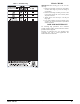
Refer to Table 4 and Fig. 23 and 24 for resistance values versus
temperature.
Table 4 – 10K/50Kohms Resistance Values vs Temperature
10Kohms
_C(_F)
TEMPERATURE RESISTANCE (ohms)
25.0 (77.0) 10.0 + / - 2.3%
0.0 (32.0) 32.6 + / - 3.2%
-28.0 (-18.4) 85.5 + / - 3.4%
50Kohm
125.0 (257.0) 1.7 + / - 1.6%
75.0 (167.0) 7.40 + / - 2.0%
25.0 (77.0) 50.0 + / - 2.3%
A91431
Fig. 23 - 10K Thermistor Resistance Versus Temperature
0
50
100
150
200
250
300
350
400
450
020406080100120
RESISTANCE (KOHMS)
TEMPERATURE (°°F)
50K THERMISTOR
A14022
Fig. 24 - 50K Thermistor Resistance Versus Temperature
If the outdoor air or coil thermistor should fail, the control will
flash the appropriate fault code (see Table 6).
IMPORTANT: The outdoor air thermistor, coil thermistor and
suction thermistor should be factory mounted in the final
locations. Check to ensure thermistors are mounted properly
(See Fig. 25, 26, 27 and 28).
Thermistor Sensor Comparison
The control continuously monitors and compares the outdoor air
temperature sensor and outdoor coil temperature sensor to ensure
proper operating conditions. The comparison is:
S In cooling if the outdoor air sensor indicates 10_F( 5.6_C)
warmer than the coil sensor (or) the outdoor air sensor indicates
25_F( 15_C) cooler than the coil sensor, the sensors are out
of range.
S In heating if the outdoor air sensor indicates 35_F( 19.4_C)
warmer than the coil sensor (or) the outdoor air sensor indicates
10_F( 5.6_C) cooler than the coil sensor, the sensors are out
of range.
If the sensors are out of range, the control will flash the appropriate
fault code as shown in Table 6.