
Zone Board Installation Manual

6616 01 1301 02
Specifications subject to change without notice.
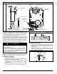
Fig. 6 − Insulate Damper
1 / " TO 2"
INSULATION
1
2
ROUND FLEXIBLE DUCTWORK
1. Slip one end of flexible ductwork over end of zone damper
(See Fig. 7).
2. Secure flexible duct to zone damper using SMACNA or
other approved method.
3. Properly seal joint using duct tape, mastic, or other
approved method. Do not allow mastic to come in contact
with actuator.
4. .If dampers are applied in an unconditioned space,
insulate damper using 1-1/2 inch to 2 inch insulation (See
Fig. 8).
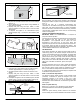
Fig. 7 − Round Flexible Ductwork
FLEXIBLE
DUCT
ZONE
DAMPER
Fig. 8 − Insulate Ductwork
/ ≤ STEEL STRAP
1
2
RECTANGULAR FIBROUS GLASS DUCTWORK
1. Insert one end of zone damper into end of fibrous glass
ductwork approximately 2 to 3 inches (See Fig. 9).
2. Use field supplied screws to secure duct board to zone
damper.
3. Properly seal joint using duct tape, mastic, or other
approved method. Do not allow mastic to come in contact
with actuator.
4. If dampers are applied in an unconditioned space, insulate
damper using 1-1/2 inch to 2 inch insulation (See Fig.10).
Fig. 9 − Rectangular Fibrous Glass Ductwork
ZONE
DAMPER
2≤ TO 3≤
FIBROUS
GLASS
DUCTWORK
FIELD
SUPPLIED
SCREWS
Fig. 10 − Insulated Rectangular Fibrous Glass Ductwork
1 / TO 2
INSULATION
1
2
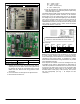
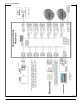
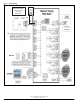
STEP 5—FINAL WIRING
Bring all damper and sensor wires together at the Observer
Zoning Panel. Make all system wiring connections as indicated
in Fig. 11.
The two DX, +DX, −R, C Observer communication bus
connections on the Observer Zoning Panel are in parallel with
each other. Use either terminal block to connect the Master
Observer wall control, Zone Room Remote Sensor(s), Observer
communicating variable-speed indoor unit and communicating
outdoor unit (if applied).
LEAVING AIR TEMPERATURE SENSOR
IMPORTANT NOTE: The ZONEXX0DTS01 is required for
proper zone board operation.
The LAS input on the Observer Zoning Panel is used to protect
the equipment from very high or very low leaving air
temperatures. The equipment will be cycled off if the
temperature is less than 45F or more than 180F. The
equipment will cycle back on when the temperature is above 45
F and below 180F and after 15 minutes have passed. The
heating and cooling LAS limits are adjustable. See the Observer
control installation instructions for more information.
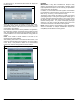
LED INDICATORS
Under normal operation, the Yellow and Green LEDs will be on
continuously (solid). If the Observer Damper Control does not
receive communications with the User Interface, the Green LED
will not be on. If a zone damper has been modulated to a
position that is not fully open or fully closed, that zone’s LED will
flash slowly, to indicate a partially open damper. If there are
faults present, the Yellow LED indicator will blink a single−digit
status code. It will blink at a fast rate, pause, then repeat.
FUSES
A 5-amp automotive type fuse is used to protect the Observer
Zoning Panel from over current on the damper drive outputs. If
this fuse fails, damper wiring should be inspected for shorts.
Also, no more than five damper motors should be connected
to a single damper output. Fuse should always be replaced with
an identical 5 amp automotive fuse.
STEP 7—Transformer Requirements
The Observer Zoning System requires a field supplied 75VA
(maximum) transformer to power the dampers. Use of the
transformer provided in the furnace or fan coil is NOT
recommended. Refer to Fig. 13 & 14 for transformer usage.
Alternate Zone Panel transformer recommended @ 60VA 24V
field supplied.
STEP 8—System Start−Up
Refer to Fig. 13 and Fig. 14 For transformer usage. Alternate
Zone Panel transformer recommended @ 60VA 24V field
supplied.
Follow the system start-up process outlined in the Observer
Communicating Zone Control Installation Instructions for details.