
Zone Board Installation Manual

4616 01 1301 02
Specifications subject to change without notice.
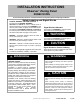
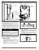
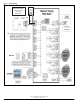
Fig. 1 − Zoning Panel and Remote Sensors
ZONING PANEL
REMOTE ROOM SENSOR
H
W
D
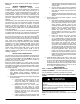
DIMENSIONS − in.(mm)
Height Width Depth
7.75 (197) 10.35 (263) 2 (51)
INSTALL Remote Room Sensors
1. Separate the sensor cover and mounting back plate by
squeezing the top and bottom of the cover together firmly
by grasping the raised top and bottom ridges. This will
release the cover. Mount to wall using provided screws
and anchors.
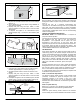
2. Pull a 4-conductor wire through hole on right-hand side.
3. Recommended connection is:
DX+ — Green = Data +
DX- — Yellow = Data -
C — White = 24 VAC (Com)
R — Red = 24VAC (Hot)
4. Push any extra wire into wall and seal hole to prevent air
leaks. Align sensor cover with base plate then press firmly
until cover snaps into place.
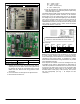
The Master Observer Wall Control and Zone Sensors should be
wired to the appropriate terminal connectors on the Observer
Zoning Panel. If the low-voltage wiring must be run alongside
line voltage wiring or near fluorescent lighting or other electrically
noisy devices, shielded cable should be used and grounded at
the common terminal on one end). The dip switch on each
OBSERVER Zone Sensor should be selected for the appropriate
zone number; for instance, Zone 2 sensor should be selected
using the DIP switch for ’off, off, off’.
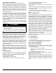
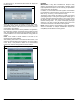
Fig. 2 − Zoning Remote Sensors
o
o
o
1
2
3
On
Zone 2
Zone ID Codes
o
o
o
1
2
3
On
Zone 3
o
o
o
1
2
3
On
Zone 4
o
o
o
1
2
3
On
Zone 5
o
o
o
1
2
3
On
Zone 6
Zone ID must be set for each Zone 2-6. ID cannot be
confirmed on Zone SensorStat. See Zone ID Codes.
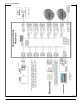
STEP 4—INSTALL ZONE DAMPERS
NOTE: Proper selection and sizing of dampers is very important
for proper system operation. Be sure to consult the Damper
Product Data Digest, and the Observer Communicating Control
specification sheet zoning section, for assistance in making
these selections. Selection and sizing information is not provided
in this installation instruction.
Zone dampers are available in round and rectangular and may
be installed in any position. Install dampers so that actuator is
visible for inspection and accessible in the event it would need to
be serviced. The black mark on the end of the damper shaft
represents position of damper blade. To wire damper, locate
terminals labeled: OPN (open); COM (common); CLS (closed;
and wire appropriately (see Fig. 1 for Damper 24 VAC
connection).