
Zone Board Installation Manual

3 616 01 1301 02
Specifications subject to change without notice.
Locating Observer Zoning Panel
NOTE: All wiring is run back to the Observer Zoning Panel.
Select a location near the Observer furnace or fan coil where
wiring from the Master Observer wall control, each Zone Remote
Room Sensor (this remote room sensor is used to sense the
temperature in a Zone, and is different from the similar part
number remote room temperature sensor used with the
Observer wall control) or CTS (Color Touch Screen) Zone
Sensor, each damper actuator, and the equipment itself can
come together easily.
The Observer Zoning Panel is approved for indoor use only and
should never be installed with any of its components exposed to
the elements. The Observer Zoning Panel (and the zone
dampers) may be installed in any area where the temperature
remains between -4° F. to 158° F. (-20° C to 70° C), and where
there is no condensation. The cover must be installed to prevent
damage from other sources. Do not locate where it will be
accessible to children.
It may be mounted in either vertical or horizontal position.
Remember that wiring access is likely the most important
consideration.
ELECTRICAL OPERATION HAZARD
Failure to follow this caution may result in damage to the unit
or improper operation.
To prevent possible damage to the Observer Zoning Panel,
do not mount on plenum, duct work, or flush against furnace.
!
CAUTION
LOCATING Observer Wall Control
The Master Observer Wall Control is the command center for the
Observer Zone System. The Master wall control should be
located where it is easily accessible and visible to the home or
business owner. It is the Zone 1 sensor and as such needs to be
located to properly measure the temperature in Zone 1.
If the Master Observer wall control cannot be installed in the
zone 1 space, a separate Remote Room Sensor (this RRS is
different for the RRS used for zones other than Zone 1, even
though the part number is similar) can be added for Zone 1 by
connecting it to the S1 and S2 terminals on the Master Observer
wall control back plate.
NOTE: The Master Observer Wall Control also controls humidity
functions. If the User Interface is not used to control Zone 1
temperature (that is, a remote room sensor is attached to the
Master Observer wall control to sense temperature), it must still
be located in a suitable area where humidity control will not be
affected.
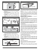
LOCATING SENSORS
For proper operation, each sensor must accurately measure the
temperature within its zone. For accurate temperature
measurement, the following guidelines should be followed:
Sensor should be mounted:
• Approximately 5 ft. (1.5m) from floor.
• Close to the center of its zone, preferably on an inside wall.
• On a section of wall without pipes or ductwork.
Sensor should NOT be mounted:
• Close to a window, on an outside wall, or next to a door leading
to the outside.
• Where it will be exposed to direct light and heat from a lamp,
sun, fireplace, or other temperature radiating object which may
cause a false reading.
• Close to or in direct airflow from supply registers.
• In areas with poor air circulation, such as behind a door or in an
alcove.
WIRING CONSIDERATIONS
Ordinary thermostat wire is ideal when wiring the Observer
Zoning System (shielded cable is not typically necessary). It is
recommended to use 18 AWG thermostat wire to install the
Observer Zoning system. For retrofit applications, 18−22 AWG
may be acceptable. Wiring lengths should not exceed 100 feet.
22 AWG wire lengths should be limited to runs of 25 feet or less.
A CTS Zone Sensor may replace the Zone Remote Room
Sensor with no wiring changes at a later date. The Observer
Wall Control requires 4 conductors, each damper actuator
requires either 2 or 3 conductors. Cut off or fold back and tape
any unneeded wires. Plan the routing of wiring early to avoid
possible problems later. Sometimes, it is a good idea to run
conduit in hard to access locations, in case a new wire must be
pulled at a later date. Remember, all wires converge at the
Observer Zoning Panel, so its location is important.
NOTE: Wiring of the Observer communication bus only requires
a four wire connection; however, it is good practice to run
thermostat cable having more than four wires in the event of a
damaged or broken wire during installation.
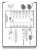
The following color code is recommended for each Observer
connection bus connection:
DX+ — Green = Data +
DX- — Yellow = Data -
C — White = 24 VAC (Com)
R — Red = 24VAC (Hot)
It is not mandatory that the above color code be used, but each
bus connection in the system MUST be wired consistently.
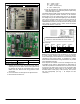
STEP 3—INSTALL COMPONENTS
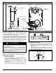
INSTALL Observer Zoning Panel
The Observer Zoning Panel is designed so that wires can enter
it from behind, above, or below. Plan wire routing before
mounting the Zoning Panel.
1. Open cover to access mounting holes.
2. Mount back plate to wall using screws and wall anchors
provided.
3. Level back plate and tighten screws.
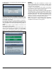
INSTALL Observer Wall Control — (see Observer Wall Control
Installation Instructions for details).
NOTE: Improper wiring of the green communication bus
connector will cause the Observer Zoning System to operate
improperly and/or fail to communicate. Check to make sure all
wiring is correct before proceeding with installation or turning on
power.