
Zone Board Installation Manual

2616 01 1301 02
Specifications subject to change without notice.
NOTE: Read the entire instruction manual before starting the
installation.
SAFETY CONSIDERATIONS
Improper installation, adjustment, alteration, service
maintenance, or use can cause explosion, fire, electrical shock,
or other conditions which may cause death, personal injury, or
property damage. Consult a qualified installer, service agency, or
your distributor or branch for information or assistance. The
qualified installer or agency must use factory−authorized kits or
accessories when modifying this product. Refer to the individual
instructions packaged with the kits or accessories when
installing.
Follow all safety codes. Wear safety glasses, protective clothing,
and work gloves. Have a fire extinguisher available. Read these
instructions thoroughly and follow all warnings or cautions
included in literature and attached to the unit. consult local
building codes, the current editions of the National Fuel Gas
Code (NFGC) NFPA 54/ANSI Z223.1, and the National Electrical
Code (NEC) NFPA 70.
In Canada refer to the current editions of the National Standards
of Canada CAN/CSA−B149.1 and .2 Natural Gas and Propane
Installation codes, and Canadian Electrical Code CSA C22.1
Recognize safety information. This is the safety−alert symbol
.
When you see this symbol on the unit and in instructions or
manuals, be alert to the potential for personal injury. Understand
these signal words: DANGER, WARNING, and CAUTION.
These words are used with the safety−alert symbol. DANGER
identifies the most serious hazards which will result in severe
personal injury or death. WARNING signifies hazards which
could result in personal injury or death. CAUTION is used to
identify unsafe practices which may result in minor personal
injury or product and property damage. NOTE is used to
highlight suggestions which will result in enhanced installation,
reliability, or operation.
INSTALLATION CONSIDERATIONS
This instruction covers the physical installation and startup of the
Observerr Zoning System and Zoning Panel. Use this instruction
to guide the actual installation process AFTER all the air side
decisions have been made. One Zoning Panel is capable of
handling up to six zones of operation.
Before the actual installation of a zoning system can begin,
decisions need to be made to determine the HVAC equipment to be
used with the zoning system, and the number and location of zones
and sensors. This affects zoning system duct layout, duct sizing,
and damper selections.
1. Consult local building and energy codes for proper
application of zoning systems. For example, California’s
2013 Building Energy Efficiency Standards for
Residential and nonresidential Buildings − Revised (aka.
“Title 24”).
2. Proper equipment selection and duct sizing are important
in a zoned system.
a. Consult industry−standard resources for duct
and zoning design. ACCA Manual D (duct
design) and Manual Zr (residential zoning
system design) are excellent resources.
b. Multiple−stage indoor and outdoor HVAC
equipment are best suited for zoning
applications. The zoning system can use the
multiple stages of equipment operation to better
match the demands of the zoning system,
especially when only one or two zones are
calling for conditioning.
c. A TXV is required on the indoor coil when used
with all residential split system equipment. This
allows the HVAC system to better respond to the
changing airflow and capacity demands of the
zoning system.
d. See the Observer Wall Control specification
sheet for the specifications for dampers to be
used with the Observer Zoning System and
Zone Panel.
e. ALWAYS use the Leaving Air Senor (aka. Duct
Temperature Sensor) with the Observer Zoning
System.
3. System static pressure and airflow regulation – bypass
duct or dump zone?
a. Indoor HVAC equipment featuring a full−feature
(aka. fully−communicating) ECM blower motor
provide CFM control features and are best for
zoning systems. Typically, these are the
modulating gas furnaces and the FCM−style air
handlers. See the equipment specification
sheets for more information. These may be
installed with either a barometric bypass
damper installed in the bypass duct, or with a
powered damper used to control airflow to a
dump zone.
b. Indoor units with all other types of blower
motors—for example, multi−tap ECM (aka
“X−
13”), PWM and PSC—should be used with a
barometric bypass damper, installed to bypass
airflow directly from the supply plenum to the
return plenum (aka. bypass duct). Allow as
much distance as possible from the indoor
equipment to where the taps for the bypass duct
are made to the supply and return plenums; this
allows better mixing of the air, and less concern
for tripping temperature limits. Sizing of the
bypass duct should be selected so that a
maximum of 25% system airflow is allowed to
bypass into the return duct. Excessive bypass
airflow can cause equipment short cycling and
reduce equipment life.
4. Install the Master Observer wall control, Color Touch
Screen (CTS) smart zone sensors, and/or Zone Room
Sensors in areas with ambient temperatures between 32°
to 104° F (0° to 40°C), with non−condensing humidity.
Install dampers and the Observer Zoning Panel in areas
with ambient temperatures between −4° to 158° F (−20° to
70° C), and non−condensing humidity.
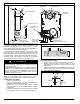
INSTALLATION
STEP 1—CHECK EQUIPMENT AND JOB SITE
INSPECT EQUIPMENT — File claim with shipping company,
prior to installation, if shipment is damaged or incomplete.
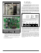
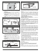
STEP 2—COMPONENT LOCATION AND WIRING CONSIDER-
ATIONS
ELECTRICAL SHOCK HAZARD
Failure to follow this warning could result in personal injury
or death.
Before installing or servicing system, always turn off main
power to system and install lockout tag. There may be more
than one disconnect switch.
!
WARNING
Disconnect supply power before routing wire.
NOTE: All wiring must comply with national, local, and state
codes.