
Service Manual


SERVICE MANUAL (C,H,T)VA9 & (C,H,T)VH8
421 08 5600 02 9
Specifications subject to change wi thout notice.
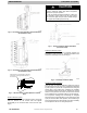
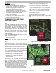
Fig. 20 – Charging in Cooling Mode CVA9, HVA9, TVA949
Fig. 21 – Charging in Cooling Mode CVA9, HVA9, TVA960
Heating Check Chart Procedure (See Fig.22 -
27)
In heating mode, the required charging method is by
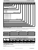
weigh- in. On new installations or complete recharge, refer
to the unit rating plate and indoor fan coil / furnace coil per
Table 1 for additional charge needed. Refrigerant charge
adjustment amount for adding or removing 0.6 oz/ft (17.74
g/m) of 3/8 liquid line above or below 15ft (4.57 m)
respectively.
To use the Heating Check Chart, operate system at
Y1+Y2–high stage. These charts indicate whether a correct
relationship exists between system operating pressure and
air temperature entering indoor and outdoor units. If
pressure and temperature do not match on chart, system
refrigerant charge may not be correct. DO NOT USE
CHART TO ADJUST REFRIGERANT CHARGE.
NOTE: High pressure is at vapor service valve. Add 12 psig
if high pressure is taken from liquid service valve.
NOTE: When charging is necessary during heating season,
charge must be weighed in accordance with unit rating
plate,
±0.6 oz./ft (±17.74 g/m). of 3/8- in. liquid- line above
or below 15 ft (4.57 m), respectively.
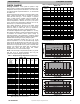
Fig. 22 – Heating Pressure Check Chart
CVH8, HVH8, TVH8 2 4
Fig. 23 – Heating Pressure Check Chart
CVH8, HVH8, TVH8 2 5
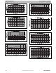
Fig. 24 – Heating Pressure Check Chart
CVH8, HVH8, TVH8 3 6
Fig. 25 – Heating Pressure Check Chart
CVH8, HVH8, TVH8 3 7
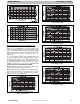
Fig. 26 – Heating Pressure Check Chart
CVH8, HVH8, TVH8 4 8