
Service Manual


SERVICE MANUAL (C,H,T)VA9 & (C,H,T)VH8
421 08 5600 02 7
Specifications subject to change wi thout notice.
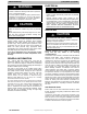
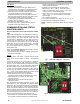
CHECK CHARGE
Charging Procedure: Force system to operate in high
stage cooling by creating a large differential between room
temperature and set point on thermostat. Use multi- meter
to verify that 24 VAC is present between C, Y1 /Y2 terminals
at outdoor unit.
Factory charge amount is shown on unit rating plate for high
stage. Target subcooling chart is provided on back of
control box door see Fig. 9 - 21 for example. To properly
check or adjust charge, condition must be favorable for
subcooling charging. Favorable conditions exists when
outdoor temperature is between 65_F(18_C) and 100_F
(38_C), and the indoor temperature is between 70_F(21_C)
and 80_F(27_C). Follow the procedure below:
Unit is factory charged for 15ft (4.57 m) of lineset. Adjust
charge by adding or removing 0.6 oz/ft (17.7 g/m) of 3/8
liquid line above or below 15ft (4.57 m) respectively.
Inaccurate charging may result in nuisance fault codes.
For standard refrigerant line lengths (80ft/24.4 m or less),
allow system to operate in cooling mode at least 25 minutes.
If conditions are favorable, check system charge by
subcooling method. If any adjustment is necessary, adjust
charge slowly and allow system to operate for 25 minutes to
stabilize before declaring a properly charged system.
If the indoor temperature is below 70_F (21.11_C), o r the
outdoor temperature is not in the favorable range, adjust
charge for line set length above or below 15ft (4.57 m) and
indoor fan coil /furnace coil per Table 1 and 2. Charge level
should then be appropriate for the system to achieve rated
capacity. The charge level should then be checked at
another time when the both indoor and outdoor
temperatures are in a more favorable range.
NOTE: If the line length is beyond 80ft (24.38 m) or greater
than 20ft (6.10 m) vertical separation see Long line
guideline for special charging requirement.
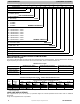
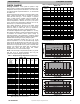
Table 1—Required Charge Adjustment for Indoor Coil
Model - HP
Furnace Coil
or
Fan Coil
Model
Number
24 25 36 37 48 60
EA*4X24 / / / / / /
EHD4X24 / / / / / /
EHD4X30 / / / / / /
F(V,C)M4X 24 - - - - / /
EA*4X30 - / / / / /
EN(A,D)4X30 - / / / / /
ENH4X36 - - - - / /
F(V,C)M4X 36 - - - - / /
EA*4X36 - - - - / /
END4X42 +.5 0 - - +.75 / /
EA*4X42 +.50 - - +.75 / /
EHD4X36 / - - +.75 / /
EHD4X42 / +.75 +.75 +.75 / /
EN(A,D)4X31 / +.75 +.75 +.75 / /
EN*4X48 / +.75 +.75 +.75 - /
EHD4X48 / +.75 +.75 +1.00 - /
EN(A,D)4X37 / / / / / /
EN(A,D)4X43 / / / / / /
EA*4X48 / / +.75 +1 .0 0 - /
EN*4X60 / / / +1.00 - -
EHD4X60 / / / +1.00 - -
F(V,C)M4X 48 / +.75 +.75 +1.00 - /
F(V,C)M4X 60 / / / +1.00 +2.2 +1.00
EA*4X60 / / / / +2.2 +1.00
EN*4X61 / / / / / /
/ = Comb. not allowed
-
= No charge adjust for ID
Note: Charge adders are in decimal format
Table 2—Required Charge Adjustment for Indoor Coil
Model - AC
Furnace Coil
or Fan Coil
Model
24 25 36 37 48 49 60
EA*4X24 - - / / / / /
EHD4X24 - - / / / / /
EHD4X30 - - / / / / /
F(V,C)M4X24 / - - / / / /
EA*4X30 - - / / / / /
EN(A,D)4X30 - - / / / / /
ENH4X36 - - - - / / /
F(V,C)M4X36 / - - - / / /
EA*4X36 - +.50 - - / / /
END4X42 +.50 +.50 - +.75 / / /
EA*4X42 +.50 +.50 - +.75 / / /
EHD4X36 +.50 +.50 - +.75 / / /
EHD4X42 +.50 +.50 +.75 +.75 / / /
EN(A,D)4X31 +.50 +1.25 +.75 +.75 / / /
EN*4X48 +.50 +1.25 +.75 +.75 - - /
EHD4X48 +.63 +1.25 +.75 +1.00 - - /
EN(A,D)4X37 +.63 +1.25 +.75 +1.00 - - /
EN(A,D)4X43 +.63 +1.25 +.75 +1.00 - - /
EA*4X48 / / +.75 +1.00 - - /
EN*4X60 / / / +1.00 - +.13 -
EHD4X60 / / / +1.00 - +.13 -
F(V,C)M4X48 .63 +1.25 +.75 +1.00 - +.13 /
F(V,C)M4X60 / / +.75 +1.00 +1.50 +.63 +1.00
/ = Comb. not allowed
- = No charge adjust for ID
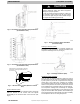
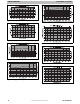
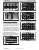
Fig. 9 – Charging in Cooling Mode CVH8, HVH8, TVH824
Fig. 10 – Charging in Cooling Mode CVH8, HVH8, TVH825
Fig. 11 – Charging in Cooling Mode CVH8, HVH8, TVH836