
Service Manual


SERVICE MANUAL (C,H,T)VA9 & (C,H,T)VH8
6 421 08 5600 02
Specifications subject to change wi thout notice.
Time Delays
The unit time delays include:
S 3.5 minute time delay after last cycle, initial power up,
return from brown - out condition. To bypass this feature,
momentarily short and release Forced Defrost pins.
S At the end of every compressor ON cycle, there will be
150 seconds of PEV open period for pressure
equalization followed by 15 seconds of PEV Off period
before the next compressor ON cycle. This delay cannot
be bypassed as it helps compressor reliability.
S 15 second delay at termination of defrost before the
auxiliary heat is de - energized.
S See Table 6 for other delay information.
S 10 minute sump warm- up delay. This delay is at the
beginning of each high voltage power up.
COMMUNICATION AND STATUS
FUNCTION LIGHTS
Observer Wall Control, Green Communications (COMM)
Light
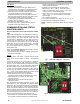
A green LED (COMM light) on the outdoor board (see Fig. 7
and 8) indicates successful communication with the other
system products. The green LED will remain OFF until
communication is established. Once a valid command is
received, the green LED will turn ON continuously. If no
communication is received within 2 minutes, the LED will be
turned OFF until the next valid communication. The green
LED will be turned off when using a standard 2- stage
non- communicating heat pump thermostat.
Amber Status Light
Amber colored STATUS light indicates operation and error
status. See Table 6 for definitions.
S Two minute time delay to return to standby operation from
last valid communication.
Defrost
This wall control (WC) offers 4 possible defrost interval
times: 30, 60 and 90 minutes, or AUTO. The default is
AUTO.
Defrost interval times: 30, 60, and 90 minutes or AUTO are
selected by the Observer Wall Control User Interface if
using UI. The 90 minute selection will default to 60 minutes
at ambient below 37_F. The UI setting will supersede the
dip s witch settings on the control board if not the same.
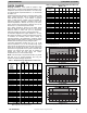
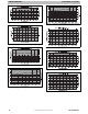
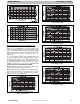
If using non- c ommunicating thermostat, defrost intervals
are set using dip switches on outdoor control board (see
Fig. 7 and 8). AUTO defrosts adjusts the defrost interval
time based on the last defrost time as follows:
S When defrost time <5 minutes, the next defrost
interval=90 minutes. (outdoor temperature above 37_F)
S When defrost time 5 - 7 minutes, the next defrost
interval=60 minutes.
S When defrost time >7 minutes, the next defrost
interval=30 minutes.
The control board accumulates compressor run time. As the
accumulated run time approaches the selected defrost
interval time, the control board monitors the coil temperature
sensor for a defrost demand. If a defrost demand exists, a
defrost cycle will be initiated at the end of the selected time
interval. A defrost demand exists when the coil temperature
is at or below 32_F(0_C) for 4 minutes during the interval. If
the c oil temperature does not reach 32_F(0_C) within the
interval, the interval timer will be reset and start over.
S Upon initial power up the first defrost interval is defaulted
to 30 minutes. Remaining intervals are at selected times.
S Defrost is only allowed to occur below 50_F(10_C)
outdoor ambient temperature.
The defrost cycle is terminated as described below.
S When OAT is > 25_F(+3.89_C), defrost terminates if
outdoor coil temperature (OCT) > 60_F (+15.6_C). And a
minimum of one (1) minute defrost length.
S When OAT ≦ 25_F(+3.89_C), defrost will terminate if
OCT is >4 5 _F(+4.4_C) and a minimum of 2 minutes
defrost length.
S Or 10 minutes has passed.
At the defrost termination, the outdoor fan will turn on 10
seconds before the reversing valve switching.
NOTE: Compressor speed during defrost will go to defrost
speed.
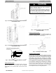
A150034
Fig. 7 – AOC Control Board for 1 and 2 Ton
A14021
Fig. 8 – AOC Control Board for 3, 4 and 5 Ton