
Service Manual


SERVICE MANUAL (C,H,T)VA9 & (C,H,T)VH8
4 421 08 5600 02
Specifications subject to change wi thout notice.
MAJOR COMPONENTS
Application Operational Control Board (AOC)
A160120
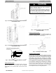
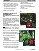
Fig. 1 – AOC (Application Operational Control) Board
The AOC board is located in the lower right hand side of
inverter tray. It’s functions include:
S Compressor speed control
S Outdoor fan motor control
S Reversing v alve operation
S Defrost operation
S Crankcase heater operation
S Pressure switch monitoring
S Time Delays
S Pressure Transducer measurements
S PEV control (pressure equalizer valve)
S Temperature measurements
S EXV (Electronic Expansion Valve) operation control
S Inverter communication and control
Inverter
The inverter is located inside the control box. This is an
air- cooled device that communicates with the control board
and drives the compressor and fan motor to the demanded
RPM. The inverter is always powered with line voltage since
no contactor is used. The inverter changes the line voltage
to DC volts and then recreates 3 phase sine waves that
vary in frequency to drive the compressor and fan motor at
the desired RPM.
NOTE: The unit may be operated with an Observer Wall
Control or a standard 2- stage HP thermostat. Observer Wall
Control will utilize 5 stages of heating and cooling, while
2- stage HP thermostat will only allow 2 discrete stages of
heating and cooling operation.
Variable Speed
Compressor
This unit contains a variable speed rotary compressor that
has a wide operating range. It operates on a variable 3
phase sine wave provided by the inverter. This compressor
can only be operated by the specific inverter supplied with
the unit.
EQUIPMENT DAMAGE HAZARD
Failure to follow this caution may result in equipment
damage and/or improper operation.
Do not attempt to apply line voltage directly to the
compressor. This will destroy the compressor.
CAUTION
!
Electronic Expansion Valve (EXV)
This unit uses an electronic expansion v alve for refrigerant
metering in the heating mode. The control board drives the
EXV to its proper position based on the operating mode and
conditions. The Observer Wall Control Service mode allows
for manual opening and closing of the EXV for
troubleshooting and pump down.
Outdoor Fan
Motor
The compact ECM outdoor fan motor is a variable - speed
brushless DC (BLDC) motor that operates at speeds from
400 to 1050 RPM. The motor is a 3- phase permanent
magnet- type motor. Just like the compressor, this motor
speed is determined by the inverter output frequency and
amplitude.
Motor speed is controlled through the inverter board in the
outdoor unit and no electronic module is attached. Motor
speed is slowed as the building load decreases, maintaining
the proper condensing temperature for both cooling and
dehumidification. As the building load increases, the motor
will increase speed until it is at maximum speed at the
maximum building load.
At unit start- up, there is a slight delay and thrust motion of
the fan motor/blade in the reverse direction, prior to
ramping- up the fan assembly.
Pressure Transducer
(SPT)
A 5 VDC output low pressure transducer that provides a 0- 5
VDC data for interpretation by the control board for a 0 to
200 psig range of pressure at the suction tube. This
interpreted pressure data is then intelligently used by the
AOC control board for low pressure cut- out, loss of charge
management, compressor protection, oil circulation
management, lubrication management and EXV control.
Pressure Equalizer Valve
(PEV)
At the end of every compressor operation (after the 3.5
minute Time Guard period), the equalizer valve opens for
150 seconds plus an additional 15 seconds of protection
before allowing the compressor to start ramping up.
The PEV is located next to the suction and discharge of the
compressor. The function of this valve is to prevent the
compressor from starting with a high refrigerant pressure
differential, thus helping the reliability of the compressor.
NOTE: A hissing sound may be heard during the
equaliz ation process. This is normal.
Outdoor Coil Thermistor
(OCT)
The outdoor coil thermistor is a 10Kohm resistor used for
multiple system operations. It provides the coil/liquid line
temperature to the heat pump board and user interface.
Low ambient operation, defrost initiation, defrost termination
and assistance with OAT temperature measurement of
some of the functions (see Fig.4) . The sensor must be
securely mounted to the tube connecting the EXV and
distributor. See Fig. 2 and Fig. 3 for proper placement. See
Table 5 for proper resistances.