
Service Manual

SERVICE MANUAL (C,H,T)VA9 & (C,H,T)VH8
421 08 5600 02 37
Specifications subject to change wi thout notice.
CAUTION
!
UNIT DAMAGE HAZARD
Failure to follow this caution may result in equipment
damage or improper operation.
To avoid filter drier damage while brazing, filter drier
must be wrapped in a heat- sinking material such as a
wet c loth.
Install Liquid- line Filter Drier
Indoor
Install filter drier as follows:
1. Braze 5 in. liquid tube to the indoor coil.
2. Wrap filter drier with damp cloth.
3. Braze filter drier to 5 in. long liquid tube from step 1.
4. Connect and braze liquid refrigerant tube to the filter
drier.
Suction Line Filter Drier
The suction line drier is specifically designed to operate with
R- 410A, use only factory authorized components. Suction
line filter drier is used in cases where acid might occur, such
as burnout. Heat pump units must have the drier installed
between the compressor and accumulator only. Remove
after 10 hours of operation. Never leave suction line filter
drier in a system longer than 72 hours (actual time).
Thermostatic Expansion Valve (TXV)
All fan coils and furnace coils will have a factory installed
thermostatic expansion valve (TXV). The TXV will be a
bi- flow, hard- shutoff with an external equalizer and a
balance port pin. A hard shut - off TXV does not have a
bleed port. Therefore, minimal equalization takes place
after shutdown. TXVs are s pecific ally designed to operate
with R- 410A or R- 22 refrigerant, use only factory
authorized TXV’s. Do not interchange R- 410A and R- 22
TXVs.
TXV
Operation
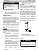
The TXV is a metering device that is used in air conditioning
and heat pump systems to adjust to c hanging load
conditions by maintaining a preset superheat temperature at
the outlet of the evaporator coil. The volume of refrigerant
metered through the valve seat is dependent upon the
following:
1. Superheat temperature is sensed by cap tube
sensing bulb on suction tube at outlet of evaporator
coil. This temperature is converted into pressure by
refrigerant in the bulb pushing downward on the
diaphragm which opens the valve via the push rods.
2. The suction pressure at the outlet of the evaporator
coil is transferred via the external equalizer tube to
the underside of the diaphragm. This is needed to
account for the indoor coil pressure drop. Residential
coils typically have a high pressure drop, which
requires this v alve feature.
3. The pin is spring loaded, which exerts pressure on
the underside of the diaphragm. Therefore, the bulb
pressure works against the spring pressure and
evaporator suction pressure to open the valve.
If the load increases, the temperature increases at the
bulb, which increases the pressure on the top side of
the diaphragm. This opens the valve and increases
the flow of refrigerant. The increased refrigerant flow
causes the leaving evaporator temperature to
decrease. This lowers the pressure on the
diaphragm and closes the pin. The refrigerant flow is
effectively stabilized to the load demand with
negligible change in superheat.
Accumulator
The accumulator is specifically designed to operate with
R- 410A or R22 respectfully; use only factory- authorized
components. Under some light load conditions on indoor
coils , liquid refrigerant is present in suction gas returning to
compressor. The accumulator stores liquid and allows it to
boil off into a vapor so it can be safely returned to
compressor. Since a compressor is designed to pump
refrigerant in its gaseous state, introduction of liquid into it
could cause severe damage or total failure of compressor.
The accumulator is a passive device which seldom needs
replacing. Occasionally its internal oil return orifice or bleed
hole may become plugged. Some oil is contained in
refrigerant returning to compressor. It cannot boil off in
accumulator with liquid refrigerant. The bleed hole allows a
small amount of oil and refrigerant to enter the return line
where velocity of refrigerant returns it to compressor. If
bleed hole plugs, oil is trapped in accumulator, and
compressor will eventually fail from lack of lubrication. If
bleed hole is plugged, accumulator must be changed. The
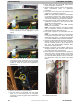
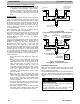
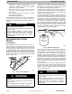
accumulator has a fusible element located in the bottom end
bell. (See Fig. 42.) This fusible element will melt at
430_F//221_C and vent the refrigerant if this temperature is
reached either internal or external to the system. If fuse
melts, the accumulator must be replaced.
A88410
Fig. 42 – Accumulator
To change accumulator:
1. Shut off all power to unit.
2. Recover all refrigerant from system.
3. Break vacuum with dry nitrogen. Do not exceed 5
psig.
NOTE: Coil may be removed for access to accumulator.
Refer to appropriate sections of Service Manual for
instructions.
PERSONAL INJURY HAZARD
Failure to follow this caution may result in personal
injury.
Wear safety glasses, protective clothing, and gloves
when handling refrigerant.
CAUTION
!
4. Remove accumulator from system with tubing cutter.
5. Tape ends of open tubing.