
Service Manual

SERVICE MANUAL (C,H,T)VA9 & (C,H,T)VH8
36 421 08 5600 02
Specifications subject to change wi thout notice.
Evacuation and recovery of refrigerant from *VA9
1. Connect gauges to *VA9 liquid and vapor service
valve ports to monitor operating pressures during and
at completion of the procedure. Attach recovery
system or vacuum pump to gauge set as needed for
the service procedure. The service valves must be
open to evacuate the unit through the line set servic e
ports.
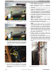
Reversing
Valve
In heat pumps, c hangeover between heating and cooling
modes is accomplished with a valve that reverses flow of
refrigerant in system. This reversing valve device is easy to
troubleshoot and replace. The reversing valve solenoid can
be checked with power off with an ohmmeter. Check for
continuity and shorting to ground. With control circuit (24v)
power on, check for correct voltage at solenoid coil. Check
for overheated solenoid.
With unit operating, other items can be checked, such as
frost or condensate water on refrigerant lines.
The sound made by a reversing valve as it begins or ends
defrost is a “whooshing” sound, as the valve reverses and
pressures in system equalize. An experienced service
technician detects this sound and uses it as a valuable
troubleshooting tool.
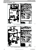
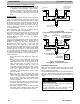
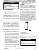
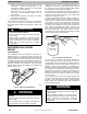
Using a remote measuring device, check inlet and outlet line
temperatures. DO NOT touch lines. If reversing valve is
operating normally, inlet and outlet temperatures on
appropriate lines should be close to each other. Any
difference would be due to heat loss or gain across valve
body. Temperatures are best checked with a remote reading
electronic- type thermometer with multiple probes. Route
thermocouple leads to inside of coil area through service
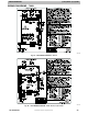
valve mounting plate area underneath coil. Fig. 40 and Fig.
41 show test points (TP) on reversing valve for recording
temperatures. Insulate points for more accurate reading.
If valve is defective:
1. Shut off all power to unit and remove charge from
system.
2. Remove solenoid coil from valve body. Remove valve
by cutting it from system with tubing cutter. Repair
person should cut in such a way that stubs can be
easily re- brazed back into system. Do not use
hacksaw. This introduces chips into system that
cause failure. After defective valve is removed, wrap it
in wet rag and carefully unbraze stubs. Save stubs for
future use. Because defective valve is not
overheated, it can be analyzed for cause of failure
when it is returned.
3. Braze new valve onto used stubs. Keep stubs
oriented correctly. Scratch corresponding matching
marks on old valve and stubs and on new valve body
to aid in lining up new valve properly. When brazing
stubs into valve, protect valve body with wet rag to
prevent overheating.
4. Use slip couplings to install new valve with stubs back
into system. Even if stubs are long, wrap valve with a
wet rag to prevent overheating.
5. After valve is brazed in, check for leaks. Evacuate
and charge system. Operate system in both modes
several times to be sure valve functions properly.
FROM INDOOR COIL
V
I
A
SERVICE VALVE ON
OUTDOOR COIL
TO
ACCUMULATOR
TO OUTDOOR
COIL
TP- 4 TP- 3
TP- 2
TP- 1
FROM COMPRESSOR
DISCHARGE LINE
A88342
Fig. 40 – Reversing Valve
(Cooling Mode or Defrost Mode, Solenoid Energized)
TO INDOOR COIL
VIA SERVICE VALVE
ON OUTDOOR COIL
TO
ACCUMULATOR
INSULATE
FOR
ACCURATE
READING
FROM
OUTDOOR
COIL
TP- 4 TP- 3
TP- 2
TP- 1
INSULATE FOR
ACCURATE
READING
FROM COMPRESSOR
DISCHARGE LINE
ELECTRONIC
THERMOMETER
A88341
Fig. 41 – Reversing Valve
(Heating Mode, Solenoid De- Energized)
Liquid Line Filter Drier
Filter driers are specifically designed for R- 22 or R- 410A
refrigerant. Only operate with the appropriate drier using
factory authorized components.
It is recommended that the liquid line drier be installed at the
indoor unit. Placing the drier near the TXV allows additional
protection to the TXV as the liquid line drier also acts as a
strainer.
CAUTION
!
UNIT DAMAGE HAZARD
Failure to follow this caution may result in equipment
damage or improper operation.
To avoid performance loss and compressor failure,
installation of filter drier in liquid line is required.