
Service Manual

SERVICE MANUAL (C,H,T)VA9 & (C,H,T)VH8
421 08 5600 02 35
Specifications subject to change wi thout notice.
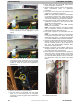
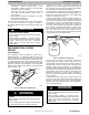
The service valves in the outdoor unit come from the factory
front - seated. This means that the refrigerant charge is
isolated from the line- set connection ports. The
interconnecting tubing (line set) can be brazed to the
service valves using industry accepted methods and
materials. Consult local codes.
Before brazing the line set to the valve, the belled ends of
the sweat connections on the service valves must be
cleaned so that no brass plating remains on either the inside
or outside of the bell joint. To prevent damage to the v alve
and/or cap “O” ring, use a wet cloth or other acceptable
heat- sinking material on the valve before brazing. To
prevent damage to the unit, use a metal barrier between
brazing area and unit.
After the brazing operation and the refrigerant tubing and
evaporator coil have been evacuated, the valve stem can
be turned counterclockwise until back - seats, which
releases refrigerant into tubing and evaporator coil. The
system can now be operated.
The service valve- stem cap is tightened to 20 2 ft/lb
torque and the service- port caps to 9 2 ft/lb torque. The
seating surface of the valve stem has a knife- set edge
against which the caps are tightened to attain a
metal- to - metal seal.
The service valve cannot be field repaired; therefore, only a
complete valve or valve stem and service- port caps are
available for replacement.
If the service valve is to be replaced, a metal barrier must be
inserted between the valve and the unit to prevent
damaging the unit exterior from the heat of the brazing
operations.
PERSONAL INJURY HAZARD
Failure to follow this caution may result in personal
injury.
Wear safety glasses, protective clothing, and gloves
when handling refrigerant.
CAUTION
!
Pumpdown & Evacuation
CAUTION
!
ENVIRONMENTAL HAZARD
Failure to follow this caution may result in environmental
damage.
Federal regulations require that you do not vent
refrigerant to the atmosphere. Recover during system
repair or final unit disposal.
If this system requires either a Pump Down or Evacuation
for any reason, the procedures below must be followed:
Pump Down
–*VH8
Because this system has an inverter controlled compressor,
suction pressure transducer and EXV, conventional
procedure cannot be used to “pump down” and isolate the
refrigerant into the outdoor unit. This procedure can only be
used in the cooling mode operation.
1. Connect gauges to *VH8 liquid and vapor serv ice
valve ports to monitor operating pressures during and
at completion of the procedure.
2. Force system to operate in high stage by creating a
large differential between room temperature and set
point on thermostat. Use multi - meter to verify that 24
VAC is present between C and Y1 and Y2 terminals
at outdoor unit.
3. Close the liquid service valve.
4. The unit will continue to run until high or low pressure
switches open. Close vapor servic e valve once c om-
pressor shuts down.
5. Remove power from indoor and heat pump unit prior
to servicing unit.
6. A quantity of charge will remain in isolated section of
system dependent on ambient temperature and
overall system charge. This charge must be
manually recovered. A recovery system will be
required to remove final quantity of refrigerant from
indoor coil and line set.
Pump Down -
*VA9
Because this system has an inverter controlled compressor,
suction pressure transducer, conventional procedure cannot
be used to “pump down” and isolate the refrigerant into the
outdoor unit. This procedure c an only be used in the cooling
mode operation.
1. Connect gauges to *VA9 liquid and vapor service
valve ports to monitor operating pressures during and
at completion of the procedure.
2. Force system to operate in high stage by creating a
large differential between room temperature and set
point on thermostat. Use multi - meter to verify that 24
VAC is present between C and Y1 and Y2 terminals
at outdoor unit.
3. Close the liquid service valve.
4. The unit will continue to run until high or low pressure
switches open. Close vapor servic e valve once c om-
pressor shuts down.
5. Remove power from indoor and outdoor unit prior to
servicing unit.
6. A quantity of charge will remain in isolated section of
system dependent on ambient temperature and
overall system charge. This charge must be
manually recovered. A recovery system will be
required to remove final quantity of refrigerant from
indoor coil and line set.
Evacuation and recovery of refrigerant from
*VH8
Refrigerant recovery and evacuation c an be performed, but
will take more time. If EXV is not forced open the recovery
and evacuation must rely on check valve as a bypass.
1. Connect gauges to *VH8 liquid and vapor serv ice
valve ports to monitor operating pressures during and
at completion of the procedure. Attach recovery
system or vacuum pump to gauge set as needed for
the service procedure. The service valves must be
open to evacuate the unit through the line set servic e
ports. The suction capillary service port is a direct
connection to the suction port of the compressor and
mayalsobeused.
2. Begin evacuation or refrigerant. Allow extra time for
refrigerant recovery and establishing a thorough
evacuation.