
Service Manual

SERVICE MANUAL (C,H,T)VA9 & (C,H,T)VH8
421 08 5600 02 31
Specifications subject to change wi thout notice.
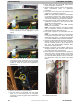
21. Route compressor harness choke to left hand side of
the top of control box and push in wire tie. Pull wires
tight as they enter control box and tighten second
wire tie.
22. Reconnect compressor power harness to the inverter.
NOTE: Reference enclosed wiring diagrams and unit
wiring diagrams in Owner’s Manual to aid in
reattaching electrical connections.
23. Triple evacuate the system below 1,000 microns.
24. Recharge unit, compensating for larger liquid line
filter. Charge compensation for oversize filter drier is
listedintheRecommended Filter/Drier Sizes table
below.
25. Check system for normal operation. If unit is a heat
pump, switch from heating to cooling a few times to
verify component operation.
Replacement Procedure for Electrical
Burnout
(System
Clean - up)
Mild Burnout
Perform steps 1 – 25 as specified in the Replacement
Procedure for Mechanical Failure and then perform steps as
follows:
26. Run unit a minimum of 2 hours and replace liquid line
filter drier.
27. Use a test kit to determine whether acceptable acid
and moisture levels have been attained. If system is
still contaminated, repeat step 17. Continue this
process until the test kit indicates “clean” system.
28. Check system for normal operation. If unit is a heat
pump, switch from heating to cooling a few times to
verify component operation.
Severe Burnout
Perform steps 1 – 22 as specified in the Replacement
Procedure for Mechanical Failure and then perform steps as
follows:
23. Clean or replace TXV.
24. Drain any trapped oil from the accumulator if used.
25. Add suction line filter drier for appropriate unit size as
indicated in Recommended Filter/Drier Sizes table
below. Mount vertical with pressure taps on both inlet
and outlet.
NOTE: On heat pumps, install suction line drier
between compressor and accumulator.
26. Triple evacuate the system below 1,000 microns.
27. Recharge unit, compensating for larger liquid line
filter. Charge compensation for oversize filter drier is
listed in Recommended Filter/Drier Sizes table below.
28. Run 1 hour minimum and change liquid line drier and
suction filter.
29. Run a minimum of 2 or more hours and change liquid
filter drier again. Remove suction line filter from
system (do not replace suction line filter).
30. Use a test kit to determine whether acceptable acid
and moisture levels have been attained. If system is
still contaminated, repeat Step 22. Continue this
process until the test kit indicates “clean” system.
31. Check system for normal operation. If unit is a heat
pump, switch from heating to cooling a few times to
verify component operation.
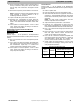
Recommended Filter/Drier Sizes
Unit
Capacity
Quantity
Minimum Required
Effective Desiccant Volume
Liquid CU. IN.
Suction CU.
IN.
1, 2, 3, 4,
and 5
1 6.5 15