
Service Manual

SERVICE MANUAL (C,H,T)VA9 & (C,H,T)VH8
30 421 08 5600 02
Specifications subject to change wi thout notice.
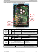
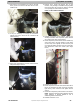
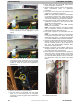
8. Remove top two screws holding control box and
remove compressor harness (highlighted in yellow
below).
9. Cut double loop wire tie on suction tube holding
compressor harness, replace with new one provided;
do not fasten at this time. Note how the compressor
harness is routed to suction tube (highlighted in
yello w below).
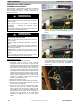
10. Remove compressor mounting hardware.
11. Cut both suction and discharge lines with tubing
cutter. Do not use brazing torch for compressor
removal as oil vapor may ignite when compressor is
disconnected.
12. Using caution and the appropriate lifting devices,
remove compressor from the unit.
13. Scratch matching marks on stubs in old compressor.
Make corresponding marks on replacement
compressor.
14. Use torch to remove stubs from old compressor and
install them in replacement compressor.
NOTE: Use appropriate protection to avoid damage
to compressor terminal cover and/or terminal box
sealant with torch flame. It is intended that terminal
cover remain installed during c ompressor installation.
15. Using caution and the appropriate lifting device, place
replacement compressor in unit and secure with
appropriate mounting hardware.
NOTE: Use of existing or new OEM mounting
hardware is recommended.
NOTE: Compressor grommet and sleeve supplied
with the compressor should be evaluated versus
OEM hardware before assembling in unit.
16. Use copper couplings to tie compressor back into
system.
NOTE: Use appropriate protection to avoid damage
to compressor terminal cover and/or terminal box
sealant with torch flame. It is intended that terminal
cover remain installed during c ompressor installation.
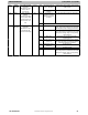
17. Remove and discard liquid line strainer and filter drier.
Replace with filter drier one size larger in capacity
than the unit being worked on (use bi- flow) type on
heat pump. See Recommended Filter/Drier Sizes
table below for appropriate size.
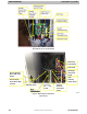
18. Reinstall compressor sound blanket making sure
discharge thermistor and compressor power harness
are routed as they were from the factory.
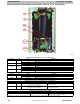
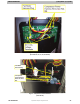
19. Route compressor power harness to new double loop
wire tie and then to the wire retainers in tube sheet
(route as they were originally to make sure they will
not contact fan blade) and then route into control box
and reinstall two control box screws. (See image
below)
20. Reinstall service panel.