
Service Manual
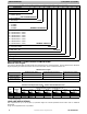


SERVICE MANUAL (C,H,T)VA9 & (C,H,T)VH8
421 08 5600 02 3
Specifications subject to change wi thout notice.
UNIT OPERATION AND SAFETY HAZARD
Failure to follow this warning could result in personal
injury or equipment damage.
R- 410A systems operate at higher pressures than
standard R- 22 systems. Do not use R - 22 service
equipment or components on R- 410A equipment.
Ensure service equipment is rated for R - 410A.
!
WARNING
CUT HAZARD
Failure to follow this caution may result in personal
injury.
Sheet metal parts may have sharp edges or burrs. Use
care and wear appropriate protective clothing and
gloves when handling parts.
CAUTION
!
Refrigeration systems contain refrigerant under pressure.
Extreme caution should be observed when handling
refrigerants. Wear safety glasses and gloves to prevent
personal injury. During normal system operations, some
components are hot and can cause burns. Rotating fan
blades can cause personal injury. Appropriate safety
considerations are posted throughout this manual where
potentially dangerous techniques are addressed.
If you do not understand any of the warnings, contact
your product distributor for better interpretation of the
warnings.
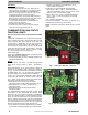
GENERAL INFORMATION
The *VH8 & VA9 split system heat pump and air
conditioners features a new outdoor cabinet design that
uses a four- sided coil design to minimize the unit footprint
and provide the best heat exchange taking full advantage of
the latest variable speed technology.
The heart of the system is the variable s peed rotary
compressor powered through the use of the variable speed
drive (VSD) inverter control. Through the use of R - 410A
refrigerant, compact ECM outdoor fan motor, VSD and
variable speed rotary compressor, along with the new
outdoor cabinet, the unit achieves a Seasonal Energy
Efficiency Ratio (SEER) of up to 19 and up to 11 Heating
Seasonal Performance Factor (HSPF).
To ensure ultimate comfort, these units should be combined
with either the FCM fan coil or Variable Speed Gas furnace
controlled with a two wire communication TSTAT0201CW
with version 5.0 software or newer. This combination will
ensure achievement of comfort with the convenience of
fingertip trouble shooting and diagnostic capability. These
units can also use a s tandard, 2- stage or single- stage
thermostat, for limited functionality.
ELECTRICAL
ELECTRICAL SHOCK HAZARD
Failure to follow this warning could result in personal
injury or death.
Exercise extreme caution when working on any
electrical components. Shut off all power to system prior
to troubleshooting. Some troubleshooting techniques
require power to remain on. In these instances, exercise
extreme caution to avoid danger of electrical shock.
ONLY TRAINED SERVICE PERSONNEL SHOULD
PERFORM ELECTRICAL TROUBLESHOOTING.
!
WARNING
Aluminum Wire
UNIT OPERAT ION AND SAFETY HAZARD
Failure to follow this caution may result in equipment
damage or improper operation.
Aluminum wire may be used in the branch circuit (such
as the circuit between the main and unit disconnect),
but only copper wire may be used between the unit
disconnect and the unit.
CAUTION
!
Whenever aluminum wire is used in branch circuit
wiring with this unit, adhere to the following
recommendations.
Connections must be made in accordance with the National
Electrical Code (NEC), using connectors approved for
aluminum wire. The connectors must be UL approved
(marked Al/Cu with the UL symbol) for the application and
wire size. The wire size selected must have a current
capacity not less than that of the copper wire specified, and
must not create a voltage drop between service panel and
unit in excess of 2 of unit rated voltage. To prepare wire
before installing connector, all aluminum wire must be
“brush- scratched” and coated with a corrosion inhibitor
such as Pentrox A. When it is suspected that connection will
be exposed to moisture, it is very important to cover entire
connection completely to prevent an electrochemical action
that will cause connection to fail very quickly. Do not reduce
effective size of wire, such as cutting off strands so that wire
will fit a connector. Proper size connectors should be used.
Check all factory and field electrical connections for
tightness. This should also be done after unit has reached
operating temperatures, especially if aluminum conductors
are used.
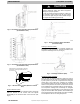
Unit Electrical Power
Power wires from the unit’s disconnect should be routed
through the power wiring hole provided at the bottom of the
unit’s c ontrol box.
Connect the ground wire to the ground connection in the
control box and connect the power wiring to the terminal
block as shown on the wiring and Installation Instructions
supplied with the unit. The unit does not require a contactor
or outdoor unit transformer in order to operate.