
Service Manual

SERVICE MANUAL (C,H,T)VA9 & (C,H,T)VH8
421 08 5600 02 29
Specifications subject to change wi thout notice.
COMPRESSOR REPLACEMENT
The following is a recommended procedure for compressor
replacement. Always refer to the unit product installation,
start - up & service instructions for detailed procedures.
!
WARNING
ELECTRICAL SHOCK HAZARD
Failure to follow this warning could result in personal
injury or death.
Turn off and lock out all power to unit before
proceeding. Discharge all capacitors before proceeding
All wiring and electric al connections shall comply with
all local and national electrical codes.
!
WARNING
PERSONAL INJURY HAZARD
failure to follow this warning could result in personal
injury.
Follow recognized safety practices and wear safety
glasses, protective clothing, and gloves. Acids formed
as a result of motor burnout can cause burns.
!
WARNING
PERSONAL INJURY HAZARD
failure to follow this warning could result in personal
injury.
do not disassemble bolts, plugs, fittings, etc. until all
pressure has been relieved from compressor.
!
WARNING
PERSONAL INJURY HAZARD
failure to follow this warning could result in personal
injury.
Do not operate compressor or provide any electrical
power to the compressor unless the terminal box cover
is in place and secured. Measurements of amps and
volts during running conditions must be taken at other
points in the power supply.
Do not provide any power to the compressor unless
suction and discharge service valves are open.
!
CAUTION
UNIT DAMAGE HAZARD
failure to follow this caution may result in equipment
damage or improper operation.
Only suction line filter driers should be used for
refrigerant and oil clean up.
Use of non - approved products could limit system life
and void unit warranty.
CAUTION
!
UNIT DAMAGE HAZARD
Failure to follow this caution may result in equipment
damage or improper operation.
Do not leave system open to atmosphere. compressor
oil is highly susceptible to moisture absorption.
At the time of compressor change out and at regular
preventative maintenance intervals the acid/moisture
content of the system should be checked using an
acid/moisture test kit. This can determine, in a few minutes,
whether acid and moisture are present in the system. No oil
sample is required. Contact your local distributor to
purchase this device.
Before Changing the
Compressor
Check compressor and associated controls to be sure
compressor replacement is necessary.
Failure
Classification
The replacement procedure is dependent on the type of
failure. The following describes the classification process:
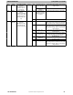
MECHANICAL FAILURES ELECTRICAL BURNOUT
1. No damage to windings
as indicated by electri-
cal check
1. Windings of compressor
open or grounded
2. Oil clean and odor free 2. Oildarkwithburnodor
3. Symptoms:Excessive
Noise Won’t Pump
Excessively Hot
3. Symptoms Blows fuses or
circuit breaker Draws ab-
normal amount of current
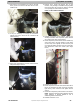
Replacement Procedure for Mechanical Failure
1. Follow all safety warnings and notices.
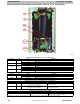
2. Precautions must be taken when servicing
components within the control box of this unit. The
technician performing the servic e must determine that
it is safe to work on or near the inverter. The electrical
disconnect that provides power to the unit must be
turned off, locked and tagged out. This will insure that
no damage will occur to the inverter, controls or other
equipment and will prevent injury if contact is made
with the electrical equipment. Wait a minimum of two
minutes before servicing the unit to allow inverter
capacitors to discharge. Follow safety instructions
located on unit control box cover.
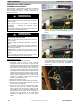
3. Remove and recover all refrigerant from system until
pressure gauges read 0 psi. Use all service ports.
Never open a system under a vacuum to atmosphere.
Break vacuum with dry nitrogen holding charge first.
Do not exceed 5 psig.
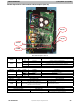
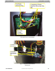
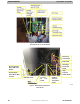
4. Remove the control box cover.
5. Disconnect compressor power harness from inverter.
6. Remove service panel to gain access to unit wiring
and compressor compartment.
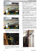
7. Cut the wire tires securing the compressor power
harness to the control box. Remove compressor
power harness (from control box). Replace wire tie
with one supplied; do not fasten at this time. The
second wire tie for the choke on the compressor is
supplied with new harness on the replacement
compressor (highlighted with the yellow circles
below).