
Service Manual

SERVICE MANUAL (C,H,T)VA9 & (C,H,T)VH8
26 421 08 5600 02
Specifications subject to change wi thout notice.
SmartSense ASSEMBLY w SHIELD GASKET
REMOVAL AND INSTALLATION Also see
figures 32 through 35
!
WARNING
ELECTRICAL SHOCK HAZARD
Failure to follow this warning could result in personal
injury or death.
Turn off the electrical supplies to the unit before
performing any maintenance or service. Follow the
operating instructions on the label attached to the unit
ELECTRICAL OPERATION HAZARD
Failure to follow this caution may result in unit damage
or improper operation.
Label all wires prior to disconnection when servicing
controls. Wiring errors can cause improper and
dangerous operation.
CAUTION
!
IMPORTANT: DO NOT USE POWER TOOLS TO TIGHTEN
THE INVERTER INPUT SCREW TERMINALS
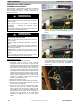
Removing Inverter:
1. Remove power to the unit. Wait a minimum of two
minutes before servicing the unit to allow inverter
capacitors to discharge. Follow safety instructions
located on unit control box cover.
2. Precautions must be taken when servicing
components within the control box of this unit. The
technician performing the servic e must determine that
it is safe to work on or near the inverter. The electrical
disconnect that provides power to the unit must be
turned off, locked and tagged out. This will insure that
no damage will occur to the inverter, controls or other
equipment and will prevent injury if contact is made
with the electrical equipment.
3. Remove the control box cover.
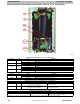
4. The inverter capacitors are covered with a protective
shield. The shield should not be removed from the
inverter.
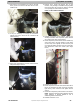
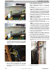
5. Before servicing the inverter, verify the inverter
voltage is zero. Measure the DC voltage at the DC +
VOLTAGE and DC - VOLTAGE terminals on the
inverter adjacent to the c apacitors to ensure that they
have totally discharged. The voltage at these
terminals must be 0 (zero) before servicing (see
following figures).
6. After verifying the voltage has dissipated to zero,
disconnect wiring from the inverter.
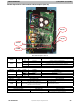
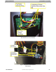
7. Disconnect three compressor power wires. Note wire
color order – Yellow, Red, and Black.
8. Disconnect fan motor power harness plug.
9. Disconnect reversing valve / PEV plug. (See Figure
Below)
10. Disconnect high pressure switch plug.
11. Disconnect EXV plug.
12. Disconnect suction pressure transducer plug.
13. Disconnect suction thermistor plug.
14. Disconnect discharge thermistor plug.
15. Disconnect OAT/OCT plug.
16. Disconnect control wiring (ABCD or thermostat
connections)
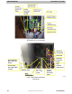
17. Disconnect two input power wires. Note wire color
order – Black and Yellow.
18. Disconnect inverter ground lead. Note wire color –
Green w/ Yellow Stripe.
19. Remove 12 mounting screws and pull out inverter
with cover intact.
Installing New
Inverter:
1. Install inverter into control box. Attach (12) mounting
screws.
2. Re- connect inverter ground lead. Note wire color –
Green w/ Yellow Stripe.
3. Re- connect two input power wires. Note wire color
order- Black and Yellow.
4. Re- connect control wiring (ABCD or thermostat
connections)
5. Re- connect OAT/OCT plug.
6. Re- connect discharge thermistor plug.
7. Re- connect suction thermistor plug.
8. Re- connect suction pressure transducer plug.
9. Re- connect EXV plug.
10. Re- connect high pressure switch plug.
11. Re - connect reversing valve / PEV plug.
12. Re- connect fan motor power harness plug.
13. Re- connect three compressor power wires. Note
wire color order- Yellow, Red and Black.
14. Replace the control box cover.
15. Apply power to the unit.