
Service Manual

SERVICE MANUAL (C,H,T)VA9 & (C,H,T)VH8
421 08 5600 02 25
Specifications subject to change wi thout notice.
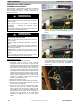
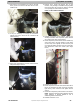
9. With using a slot screwdriver, lift up the on the side
tab to pry the cover off from the RTV. Be sure not to
break the tab.
10. It may be necessary to leverage the screwdriver
against cover next to tab so as not to break the tab
while loosening.
11. Once Cover is loosened on one side, use screwdriver
along freed edge to remove.
12. Remove cover, unplug old harness, plug in new
harness, verify bushing is reinstalled and plug leads
leave the terminal box through the bushing; reinstall
cover pushing one side down then the other.
NOTE: DO NOT SCRAP SEALANT
13. Reinstall compressor sound blanket making sure
discharge thermistor and compressor power harness
are routed as they were from the factory.
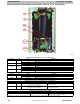
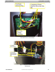
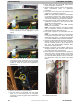
14. Route compressor power harness to new double loop
wire tie and then to the wire retainers in tube sheet
(route as they were originally to make sure they will
not contact fan blade) and then route into control box
and reinstall two control box screws. (See image
below)
15. Reinstall service panel.
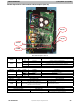
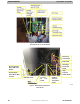
16. Route compressor harness choke to left hand side of
the top of control box and push in wire tie. Pull wires
tight as they enter control box and tighten second
wire tie.
17. Reconnect compressor power harness to the inverter.
NOTE: Reference enclosed wiring diagrams and unit
wiring diagrams in Owner’s Manual to aid in
reattaching electrical connections.
18. Reinstall control box cover.