
Service Manual

SERVICE MANUAL (C,H,T)VA9 & (C,H,T)VH8
24 421 08 5600 02
Specifications subject to change wi thout notice.
COMPRESSOR POWER HARNESS
ASSEMBLY REPLACEMENT
The following is a recommended procedure for compressor
power harness replacement. Always refer to the unit
product installation, start- up & service instructions for
detailed procedures.
!
WARNING
ELECTRICAL SHOCK HAZARD
Failure to follow this warning could result in personal
injury or death.
Turn off and lock out all power to unit before
proceeding. Discharge all capacitors before
proceeding
All wiring and electric al connections shall comply with
all local and national electrical codes.
!
WARNING
ELECTRICAL SHOCK HAZARD
Failure to follow this warning could result in personal
injury or death.
failure to follow this warning could result in personal
injury.
Do not operate compressor or provide any electrical
power to the compressor unless the terminal box cover
is in place and secured.
Measurements of amps and volts during running
conditions must be taken at other points in the power
supply.
Do not provide any power to the compressor unless
suction and discharge service valves are open.
Replacement
Procedure
1. Follow all safety warnings and notices.
2. Precautions must be taken when servicing
components within the control box of this unit. The
technician performing the servic e must determine that
it is safe to work on or near the inverter. The electrical
disconnect that provides power to the unit must be
turned off, locked and tagged out. This will insure that
no damage will occur to the inverter, controls or other
equipment and will prevent injury if contact is made
with the electrical equipment. Wait a minimum of two
minutes before servicing the unit to allow inverter
capacitors to discharge. Follow safety instructions
located on unit control box cover.
3. Remove the control box cover.
4. Disconnect compressor power harness from inverter.
5. Remove service panel to gain access to unit wiring
and compressor compartment.
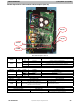
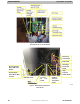
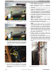
6. Cut the wire tires securing the compressor power
harness to the control box. Remove compressor
power harness (from control box). Replace wire tie
with supplied wire tie; do not fasten at this time. The
second wire tie for the choke on the compressor is
supplied with new harness on the replacement
compressor (highlighted with the yellow circles
below).
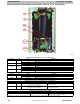
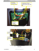
7. Remove top two screws holding control box and
remove compressor harness (highlighted in yellow
below).
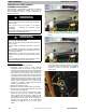
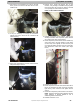
8. Cut double loop wire tie on suction tube holding
compressor harness, replace with new one provided;
do not fasten at this time. Note how the compressor
harness is routed to suction tube. (Highlighted in
yello w below)