
Service Manual


SERVICE MANUAL (C,H,T)VA9 & (C,H,T)VH8
12 421 08 5600 02
Specifications subject to change wi thout notice.
A12035
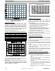
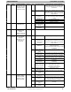
Fig. 28 – Suction Pressure Transducer (SPT)
Output Function Graph
Temperature
Thermistors
Thermistors are electronic devices which sense
temperature. As the temperature increases, the resistance
decreases. 10Kohm thermistors are used to sense outdoor
air temperature (OAT), coil temperature (OCT) and the
suction line temperature (OST) located between the
reversing valve and the accumulator. A 50Kohm thermistor
is used to sense discharge temperature (ODT).
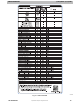
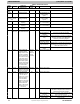
Refer to Table 5 and Figs. 29 and 30.
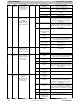
Table 5—10K/50K Resistance Values vs Temperature
10Kohm _C(_F)
TEMPERATURE RESISTANCE (ohms)
25.0 (77.0) 10.0 + / - 2.3%
0.0 (32.0) 32.6 + / - 3.2%
-28.0 (-18.4) 85.5 + / - 3.4%
50Kohm
125.0 (257.0) 1.7 + / - 1.6%
75.0 (167.0) 7.40 + / - 2.0%
25.0 (77.0) 50.0 + / - 2.3%
A91431
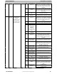
Fig. 29 – 10K Thermistor Resistance Vs Temperature
If the outdoor air or coil thermistor should fail, the control will
flash the appropriate fault code (see Table 6).
IMPORTANT: The outdoor air thermistor, coil thermistor and
suction thermistor should be factory mounted in the final
locations. Check to ensure thermistors are mounted
properly(SeeFig.2,3,4,5and6).
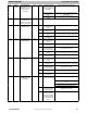
0
50
100
150
200
020406080100120
RESISTANCE (KOHMS)
TEMPERATURE (C)
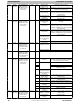
THERMISTOR CURVE
A14022
Fig. 30 – 50K Thermistor Resistance Vs Temperature
Thermistor Sensor
Comparison
The control continuously monitors and compares the
outdoor air temperature sensor and outdoor coil
temperature sensor to ensure proper operating conditions.
The comparison is:
S In cooling if the outdoor air s ensor indicates 10_F
(5.6_C) warmer than the coil sensor (or) the outdoor air
sensor indicates 25_F(15_C) cooler than the c oil
sensor, the sensors are out of range.
S In heating if the outdoor air s ensor indicates 35_F
(19.4_C) warmer than the coil sensor (or) the outdoor air
sensor indicates 10_F(5.6_C) cooler than the coil
sensor, the sensors are out of range.
If the sensors are out of range, the control will flash the
appropriate fault code as shown in Table 6.
The thermistor comparisons are not performed during low
ambient cooling or defrost operation.
Failed Thermistor Default
Operation
Factory defaults have been provided in the event of failure
of outdoor air thermistor (OAT) and/or outdoor coil thermistor
(OCT).
If the OAT sensor should fail, defrost will be initiated based
on coil temperature and time.
If the OCT sensor should fail, defrost will occur at each time
interval during heating operation, but will terminate after 2
minutes.
If there is a thermistor out- of - range error, defrost will occur
at each time interval during heating operation, but will
terminate after 2 minutes.
Count the number of short and long flashes to determine the
appropriate flash code. Fig. 31 and Table 6 gives possible
causes and actions related to each error.
Maximum Power Mode - Inverter over
Temperature
The outdoor unit is equipped with inverter temperature
sensing. If the inverter senses a temperature above the high
threshold limit, it will respond as follows:
1. Display the local fault code only on the AOC Status
LED.
2. The system will continue to run, but attempt to
mitigate by speed reduction.
3. When the system demand is satisfied, the unit will
shut down.
4. If the fault is still active on the AOC Status LED, the
ODF will c ontinue to run at 500 rpm until the inverter
temperature falls below the threshold.
5. The c ompressor will not restart if the fault is still
active.