
Service Manual


SERVICE MANUAL (C,H,T)VA9 & (C,H,T)VH8
421 08 5600 02 11
Specifications subject to change wi thout notice.
UNIT DAMAGE HAZARD
Failure to follow this caution may result in equipment
damage and/or improper operation.
Do not use Meggar for measuring the winding
resistance.
CAUTION
!
UNIT DAMAGE HAZARD
Failure to follow this caution may result in equipment
damage and/or improper operation.
To maintain water integrity of the compressor fusite
terminal box, the two holes in outer ring need to be full
of RTV sealant.
CAUTION
!
Fan Motor
If verification of proper operation is required for the fan
motor used in this unit, follow these steps:
1. Disconnect fan motor connector from control board.
2. Measure resistance between any 2 of the 3 leads
present.
3. Compare measurement to values below
Fan Motor Resistance
Unit Size Resistance (Ohms)
24 21.2
25, 36, 37, 48, 49 (AC), 60 11.1
Occasionally the unit may become unresponsive due to
certain combinations of previous fault codes. There may
not be anything wrong with the unit or components. The
unit may require a high voltage power cycling for at
least 2 minutes or longer to clear the condition. If the
condition persists, conduct further troubleshooting per
the service manual.
!
ATTENTION
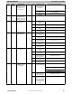
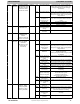
Control Fault
If the outdoor unit control board has failed, the control will
flash the appropriate fault code (see Table 6). The control
board should be replaced.
Brown- Out
Protection
If the line voltage is less than 187V for at least 4 seconds,
the Compressor and OD fan goes to 0 rpm. Compressor
and fan operation are not allowed until voltage is a minimum
of 190V. The control will flash the appropriate fault code
(see Table 6).
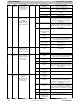
230V Line (Power Disconnect)
Detection
The control board senses the presence of absence of 230V
through inverter feedback. Voltage should present at all
times when system is in service regardless if system is
running or standby. If there is no 230V at the inverter when
the indoor unit is powered with a cooling or heating demand,
the appropriate fault code is displayed on WC
(communicating only – see Fig. 31). If system is configured
with conventional heat pump thermostat
(non- communicating), no fault code will be displayed on
AOC board, nor will any status LEDs be lit. Use multimeter
to check for the presence of 230V in this situation.
High Pressure Switch
Protection
The outdoor unit is equipped with high pressure switch. If
the control senses the opening of a high pressure switch
(open 600+/- 5 psig, close 470+/ - 10 psig @77_F), it will
respond as follows:
1. Display the appropriate fault code (see Fig. 31).
2. After a 6 minute delay, if there is a call for cooling or
heating and HPS is reset, the PEV opens for 150
seconds to equalize system pressures. Compressor
and fan will then ramp to the next lower stage of oper-
ation until demand is satisfied. Staging down and re-
setting to the highest stage will end after 2 hours of
accumulated operation without further HPS trips.
3. A system malfunction will occur after repeated HPS
faults and the stage has reached the lowest level.
This could take five c onsecutive HPS trips if the first
occurred in stage 5 demand, or 1 HPS trip if in stage
1 demand.
4. In the event of a high- pressure switch trip or high-
pressure lockout, check the refrigerant charge,
outdoor fan operation, and outdoor coil (in cooling) for
airflow restrictions, or indoor airflow in heating.
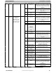
Low Pressure
Protection
The outdoor unit is equipped with suction pressure
transducer. If suction pressure drops below 15 psi at any
time, or below 33 psi for 5 minutes, the compressor and fan
will stop running and an error code will be displayed on user
interface.
1. If there is still a demand for unit operation after the 15
minute delay and pressure has increased to >43psi
(cooling) and >35psi (heating) , system will resume
operation.
2. If there are three (3) consecutive trips because of
suction pressure dropping below 15 psi, the low
pressure switch will lock out operation for 4 hours.
Trip counter will be reset after 15 minutes of
successful operation.
3. When a change in demanded stage occurs, suction
pressure is checked at each stage in between current
and demanded stage. This is to prevent ramping of
compressor speed too quickly and creating a low
pressure situation. As long as suction pressure is
>=45psi, the compressor is able to ramp to next
stage. If suction pressure is lower than required,
additional wait time at current stage will occur.
4. In the event of a low- pressure trip or low- pressure
lockout, check the refrigerant charge and indoor
airflow (cooling) and outdoor fan operation and
outdoor coil in heating.
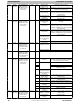
Suction Pressure Transducer
(SPT)
If accuracy of the transducer is questioned, the technician
can check it while it is attached to the AOC board. Connect
a gage manifold to the suction valve gage port fitting.
At the AOC board, with the wire harness receptacle
exposing a portion of the three pins on the AOC board, a
DC voltmeter can read the DC voltage between ground and
supply (input) terminal. Ensure that the input voltage is 5
VDC. Next, read the DC voltage across the ground and
output terminal. Record the output voltage.
The suction pressure that the pressure transducer is
reading can be calculated by taking the output voltage and
subtracting 0.5 from it then taking that difference and
multiplying it by 50. Pressure (psig) = 50.0 x (DCV out -
0.5). For example, if the measured voltage is 3.0 VDC:
50 X (3.0 - 0.5) = 50 X 2.5 = 125 psig. See Fig. 28.