
Service Manual


SERVICE MANUAL (C,H,T)VA9 & (C,H,T)VH8
10 421 08 5600 02
Specifications subject to change wi thout notice.
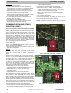
Fig. 27 – Heating Pressure Check Chart
CVH8, HVH8, TVH8 60
TROUBLESHOOTING
Systems Communication Failure
If communication is lost with the wall control (WC), the green
LED will go out. Check the wiring to the wall contro l and the
indoor and outdoor units and power.
Model
Plug
Each control board contains a model plug. The correct
model plug must be installed for the system to operate
properly (see Table 3).
The model plug is used to identify the type and size of unit
to the control.
On new units, the model and serial numbers are inputted
into the AOC board’s memory at the factory. If a model plug
is lost or missing at initial installation, the unit will operate
according to the information input at the factory and the
appropriate error code will flash temporarily. An RCD
replacement AOC board contains no model and serial
information. If the factory control board fails, the model plug
must be transferred from the original board to the
replacement board for the unit to operate.
When installing heat pump with older fan coils , a model plug
change may be required.
NOTE: The model plug takes priority over factory model
information input at the factory. If the model plug is removed
after initial power up, the unit will operate according to the
last valid model plug installed, and flash the appropriate
fault code temporarily.
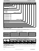
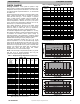
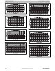
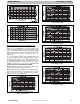
Table 3—Factory Supplied Model Plug Information
CVH8, HVH8,
TVH8
FAST PART
NUMBER
PIN RESISTANCE (K- OHMS)
Pins 1 - 4
(R1)
Pins 2 - 3
(R2)
24 1184941 18K 75K
25 1188069 18K 11K
36 1184943 18K 120K
37 1188070 18K 24K
48 1184945 18K 180K
60 1184947 18K 270K
CVA9, HVA9,
TVA9
FAST PART
NUMBER
Pins 1 - 4
(R1)
Pins 2 - 3
(R2)
24 1184942 18K 91K
25 1188023 18K 5.1K
36 1184944 18K 150K
37 1188024 18K 18K
48 1184946 18K 220K
49 1188025 18K 33K
60 1184948 18K 360K
Status Codes
Table 6 shows the status codes flashed by the amber status
light. Most system problems can be diagnosed by reading
the status code as flashed by the amber status light on the
control board.
The codes are flashed by a series of short and long flashes
of the status light. The short flashes indicate the first digit in
the status code, followed by long flashes indicating the
second digit of the error code.
The short flash is 0.25 seconds ON and the long flash is 1.0
second ON. Time between flashes is 0.25 seconds. Time
between short flash and firs t long flash is 1.0 second. Time
between code repeating is 2.5 seconds with LED OFF.
Codes are easily read from wall control (WC)
EXAMPLE:
3 short flashes followed by 2 long flashes indicates a 32
code. Table 6 shows this to be low pressure switch open.
Status Code Recall Mode
Active status codes are stored in memory even when power
is absent. The most recently flashing status code (highest
priority active) can be recalled from memory via status code
recall mode and displayed using the amber LED. The status
code recall mode is accessed by shorting (use a clip wire)
the “force defrost” connector (labeled J2 on the board) and
then power ON the unit. Please make sure the unit is turned
OFF before shorting the pins. Status call recall mode will
continue as long as the “force defrost” terminals remain
shorted. The unit will not attempt to heat or cool while the
terminals remain shorted. Once the status code is read,
power down the unit and remove the s hort.
Variable Speed Compressor Winding
Resistance
This compressor operates with 3 - phase variable frequency
PWM variable voltage. For troubleshooting fault codes
related to compressor resistances, follow these steps:
1. Disconnect compressor power leads from the inverter
MOC terminals, U (YEL), V (RED), and W (BLK).
2. Measure the resistance between YEL to RED, YEL to
BLK, and RED to BLK and compare to Table 4 val-
ues. Each resistance set should be equal.
3. Measure the resistance to ground for each lead.
4. If the resis tances check out, reconnect power leads to
appropriate terminal.
5. If the resistances appear to be abnormal, it will be
necessary to measure the resistance at the
compressor fusite terminals.
6. During the removal of the compressor fusite cap, do
not remove the RTV sealant. Remove the harness
plug, measure resistances, and compare to Table 4.
7. Special care will need to be taken with the
replacement of the compressor fusite cap. Make sure
the two holes in the compressor fusite terminal box
are still full of RTV sealant before the cap is
reinstalled. The factory RTV can be reused as long as
none of it has been removed during the cap removal.
8. Reinstall compressor sound blanket making sure
discharge thermistor and compressor power harness
are routed as they were from the factory
Table 4—Variable Speed Compressor Resistance
(winding resistance at 70_F 20_F)
WINDING
(between)
MODEL *VH8 (Ohms)
24 25 36 37, 48 49 (AC), 60
terminals
1.13
OHM
.59
OHM
.59
OHM
.37
OHM
.24 OHM
terminal & ground >1 mega OHM