
Product Specifications
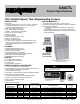
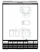


PRODUCT SPECIFICATIONS Gas Furnace: G80CTL
6 441 51 3500 01
Specifications subject to change without notice.
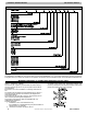
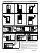
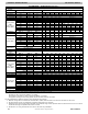
DOWNFLOW VENT CONFIGURATIONS
SEE NOTES: 1,2,4,5,7,8,9
A02061
SEE NOTES: 1,2,4,5,6,7,8,9
A02062
SEE NOTES: 1,2,3,4,5,7,8,9 A02063
DOWNFLOW CONTINUTED UPFLOW VENT CONFIGURATIONS
SEE NOTES:1,2,3,4,5,7,8,9 A02060
A02058SEE NOTES: 1,2,4,7,8,9
SEE NOTES: 1,2,3,4,7,8,9
A02059
HORIZONTAL RIGHT VENT CONFIGURATIONS
SEE NOTES: 1,2,4,5,7,8,9
A02070
SEE NOTES: 1,2,4,5,7,8,9 A02068
SEE NOTES: 1,2,4,7,8,9
A02069
HORIZONTAL LEFT VENT CONFIGURATIONS
SEE NOTES: 1,2,4,7,8,9
A02064
SEE NOTES: 1,2,4,5,7,8,9
A02065
SEE NOTES: 1,2,4,5,7,8,9
A02066
HORIZONTAL LEFT VENT CONFIGURATIONS
SEE NOTES: 1,2,4,5,7,8,9
A02067
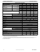
Venting Notes
1. For common vent, vent connector sizing and vent material: United States−use the NFGC.
2. Immediately increase to 5 inch (102 mm) or 6 inch (152 mm) vent connector outside furnace
casing when 5 inch (127 mm) vent connector is required, refer to Note 1 above.
3. Side outlet vent for upflow and downflow installations must use Type B vent immediately af-
ter exiting the furnace, expect when Downflow Vent Guard Kit is used in the downflow posi-
tion.
4. Type−B vent where required, refer to Note 1 above.
5. A 4 inch(102 mm) single−wall (26 ga. min.) vent must be used inside furnace casing and
when the NAHB00301VC Downflow Vent Guard Kit is used external to the furnace.
6. Accessory Downflow Vent Guard Kit is required in downflow installations with lower vent
configuration.
7. Chimney Adapter Kit may be required for exterior masonry chimney applications. Refer to
Chimney Adapter Kit for sizing and complete application details.
8. Secure vent connector to furnace elbow with (2) corrosion−resistant sheet metal screws,
spaced approximately 180_ apart.
9. Secure all other single wall vent connector joints with (3) corrosion resistant screws spaced
approximately 120_ apart. Secure Type−B vent connectors per vent connector manufactur-
er’s recommendations.