
Installation Manual


19
616 01 1019 01
NOTE: In a dual fuel installation with a non-communicating
heat pump, an OAT sensor must be installed, or the heat
pump will not run.
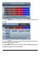
Shielded Wire
If the thermostat wiring will be located near or in parallel with
high voltage wiring, cable TV or Ethernet wiring, then shiel-
dedthermostatwirecanbeusedtoreduceoreliminatepo-
tential interference. The shield wire should be connected to
the C terminal, or ground, at the indoor unit. The shield wire
should NOT be connected to any terminal at the wall control.
Connecting the shield to ground at both ends can cause cur-
rent loops in the shield, reducing shield effectiveness.
Non-communicating equipment
The Observer
®
Control, when paired with the NAXA00101DB
daughter board, will operate non-communicating equipment.
When the system utilizes the NAXA00101DB daughter
board, the Observer Control operates as a standard univer-
sal thermostat. See Appendix Wiring Diagrams
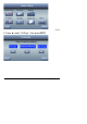
Mounting
First become familiar with all plastic assembly pieces shown
in Figure 2. The wall control will snap together with the
back-plate. A back-plate is supplied Figure 2. Attach
back-plate using only a small hole in the wall allowing a four
wire connection to pass through. Mount the assembly to the
back-plate.
NOTE: Once Observer Control is secured to wall with the
back-plate assembly (snapped together), care must be taken
not to bend or break the interlocking tabs when removing.