
Installation Manual


9 421 01 5900 02
Specifications subject to change without notice.
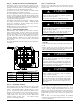
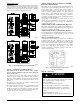
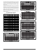
Fig. 15 - Charging in Cooling Mode CVA9, HVA9, TVA949
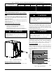
Fig. 16 - Charging in Cooling Mode CVA9, HVA9, TVA960
Step 13 — Pumpdown & Evacuation
CAUTION
!
ENVIRONMENTAL HAZARD
Failure to follow this caution may result in environmental
damage.
Federal regulations require that you do not vent refrigerant to
the atmosphere. Recover during system repair or final unit
disposal.
If this system requires either a Pump Down or Evacuation for any
reason, the procedures below must be followed:
Pump Down
Because this system has an inverter controlled compressor, suction
pressure transducer, conventional procedure cannot be used to
“pump down” and isolate the refrigerant into the outdoor unit.
1. Connect gauges to CVA9, HVA9, TVA9 liquid and vapor
service valve ports to monitor operating pressures during
and at completion of the procedure.
2. Force system to operate in high stage by creating a large
differential between room temperature and set point on
thermostat. Use multi- meter to verify that 24 VAC is
present between C and Y1 and Y2 terminals at outdoor unit.
3. Close the liquid service valv e.
4. The unit will continue to run until high or low pressure
switches open. Close vapor service valve once compressor
shuts down.
5. Remove power from indoor and outdoor unit prior to
servicing unit.
6. A quantity of charge will remain in isolated section of
system dependent on ambient temperature and overall
system charge. This charge must be manually recovered. A
recovery system will be required to remove final quantity of
refrigerant from indoor coil and line set.
Evacuation and recovery of refrigerant from CVA9,
HVA9, TVA9
1. Connect gauges to CVA9, HVA9, TVA9 liquid and vapor
service valve ports to monitor operating pressures during
and at completion of the procedure. Attach recovery system
or vacuum pump to gauge set as needed for the service pro-
cedure. The service valves must be open to evacuate the
unit through the line set service ports.
2. Begin evacuation or refrigerant. Allow extra time for refrig-
erant recovery and establishing a thorough evacuation.
MAJOR COMPONENTS
Variable Speed Control Board
A160120
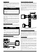
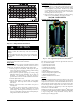
Fig. 17 - AOC (Application Operational Control) Board
The AOC board is located in the lower right hand side of inverter
tray. It’s functions include:
S Compressor speed control
S Outdoor fan motor control
S Crankcase heater operation
S Pressure switch monitoring
S Time Delays
S Pressure Transducer measurements
S PEV control (pressure equalizer valve)
S Temperature measurements
S Inverter communication and control
Inverter
The inverter is located inside the control box. This is an air- cooled
device that communicates with the control board and drives the
compressor and fan motor to the demanded RPM. The inverter is
always powered with line voltage since no contactor is used. The
inverter changes the line voltage to DC volts and then recreates 3
phase sine waves that vary in frequency to drive the compressor
and fan motor at the desired RPM.
NOTE: The unit may be operated with an Observer
®
Wall Control
or a standard 2- stage thermostat. Observer Wall Control will utilize
5 stages cooling, while 2- stage thermostat will only allow 2
discrete stages of cooling operation.