
Installation Manual


7 421 01 5900 02
Specifications subject to change without notice.
CAUTION
!
PERSONAL INJURY HAZARD
Failure to follow this caution may result in personal injury .
Wear safety glasses, protective clothing, and gloves when
handling refrigerant.
CAUTION
!
ENVIRONMENTAL HAZARD
Failure to follow this caution may result in environmental
damage.
Federal regulations require that you do not vent refrigerant to
the atmosphere. Recover during system repair or final unit
disposal.
Step 11 — System Functions and Sequence of
Operation
The CVA9, HVA9, TVA9 models utilize either Observer
®
Wall
Communicating Wall Control or conventional thermostat. When
using Wall Control controls, a call for cooling will energize the
outdoor fan and compressor to run at lowest cooling demand. If
this does not satisfy cooling demand, the system will ramp up in
stages until it satisfies the demand. After coping with the higher
demand, the unit returns to lower capacity operation until the
demand is satisfied or until an increase in demand. When using a
conventional thermostat, the thermostat controls the staging of
outdoor unit.
Upon initial start- up (or any power cycle) of the unit there will be
a 5 - minute delay before the unit will start, once a call for heating
or cooling is given. The compressor will then ramp to stage 2 and
operate there for one minute. When the one- minute time has
elapsed, status code 68 will be generated and the system will
continue to operate at stage 2 for 10 minutes. This operation is
important to system reliability and cannot be bypassed. Each time
high voltage is removed and reapplied, this behavior will be
repeated.
When the 10 minutes has elapsed, the unit will ramp to the
called- for stage. It will take approximately three additional minutes
to get to high - stage compressor RPM.
When all demand is satisfied, the compressor will shut off. As the
unit operates at lower capacity, system vapor (suction) pressure will
be higher than it is during a standard single- stage system operation
or during a higher capacity operation.
The Observer Wall Control displays the operation mode and fault
codes as specified in the troubleshooting section. See Table 6 for
codes and definitions.
The conventional thermostat inputs are designed to work with most
indoor units. See AHRI for approved combinations. Connections
are Y/Y2, Y1, R and C. Depending on thermostat and indoor unit,
the system will operate at 1 or 2 capacities in cooling mode.
NOTE: Only one code will be displayed on the outdoor unit
control board (the most recent, with the highest priority). The
latest codes are stored and can be accessed via the Observer Wall
Control.
Upon a call for cooling through the Observer Wall Control (or the
Y1 and/or Y2 connections in a non - communicating system), the
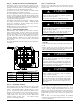
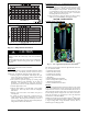
Application Operation Control (AOC) board (see Fig. 17) will
request a compressor speed and outdoor fan motor speed based on
the indoor space demand and outdoor conditions.
If the conditions are correct for operation, the control board will
allow the requested operation to begin, but if the control board
determines that the conditions are not correct, the board will decide
what other operation nearing that condition is acceptable.
The inverter Motor Operational Control (MOC) then outputs the
three- phase PWM signal and frequency that gently ramps the
compressor speed up to stage 2, and then will adjust to the
demanded speed. The gentle ramp - up results in no locked rotor
amps to the compressor motor. The unit nameplate for compressor
LRA will be stamped N/A (not applicable).
During operation, the AOC monitors itself and the compressor
operation along with the system pressures and temperatures. The
MOC board monitors the temperature, current and operational
status of the compressor, OD fan and the inverter itself. During
operation, the compressor speed will be adjusted to meet the
changes to the demand.
Outdoor Fan Motor Operation
The compact ECM outdoor fan motor is a variable-speed brushless
DC (BLDC) motor that operates at speeds from 400 to 1050 RPM.
The motor is a 3- phase permanent magnet- type motor. Just like
the compressor , this motor speed is determined by the inverter
output frequency and amplitude. (Fig. 9)
Motor speed is controlled through the inverter board in the outdoor
unit and no electronic module is attached. Motor speed is slowed as
the building load decreases, maintaining the proper condensing
temperature for both cooling and dehumidification. As the building
load increases, the motor will increase speed until it is at maximum
speed at the maximum building load.
At unit start- up, there is a slight delay and thrust motion of the fan
motor/blade in the reverse direction, prior to ramping- up the fan
assembly .
A14021
Fig. 9 - AOC Control Board
Step 12 — Check Charge
Charging Procedure: Force system to operate in high stage
cooling by creating a large differential between room temperature
and set point on thermostat. If using conventional 2- stage
thermostat, use multi- meter to verify that 24 VAC is present
between C, Y1 /Y2 terminals at outdoor unit.
Factory charge amount is shown on unit rating plate for high stage.
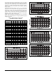
Target subcooling chart is provided on back of control box door
see Fig. 10 - 16 for example. To properly check or adjust charge,
condition must be favorable for subcooling charging. Favorable
conditions exists when outdoor temperature is between 65_F
(18_C) and 100_F(38_C), and the indoor temperature is between
70_F(21_C) and 80 _F(27_C). Follow the procedure below:
Unit is factory charged for 15ft (4.57 m) of lineset. Adjust charge
by adding or removing 0.6 oz/ft (17.7 g/m) of 3/8 liquid line above
or below 15ft (4.57 m) respectively.