
Installation Manual


421 01 5900 02 6
Specifications subject to change without notice.
Final Wiring Check
IMPORTANT: Check factory wiring and field wire connections to
ensure terminations are secured properly. Check wire routing to
ensure wires are not in contact with tubing, sheet metal, etc. Ensure
that high and low voltage is separated where possible, to minimize
induced noise from VFD to communication wiring.
A160119
A160118
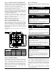
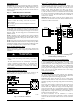
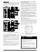
Fig. 7 - Low Voltage Wiring (Non- Communicating)
Step 8 — Compressor Crankcase Heater
This compressor has an internal crankcase heater. Furnish
power to the unit a minimum of 24 hours befo re starting the
unit for the first time.
Upon initial start- up of unit, status code 68 will be generated and
system will operate at stage 2 for 11 minutes. This operation is
important to system reliability and cannot be bypassed. Each time
high voltage is removed and reapplied this behavior will be
repeated.
To furnish power to heater only, set thermostat to OFF and close
electrical disconnect to outdoor unit.
Power is not required to the indoor unit or Observer
®
Wall Control
for proper operation of heater. Crankcase heater will be
intelligently energized as needed between operations, even when
the Observer Wall Control or thermostat and indoor unit is not
installed, as long as there is power to the outdoor unit.
Airflow Setup for Observer Furnace or FCM4X
Fan Coil (communicating)
This system can only be installed with communicating indoor and
Observer Wall Control TSTAT0201CW software version 5.0 or
greater. When using a Observer Wall Control, airflow is
automatically selected based on equipment size. The user has the
option of selecting Comfort, Efficiency and Max airflow for
Cooling modes. These should be selected based on balance
between the homeowner’s comfort and energy consumption
expectations. See Observer Wall Control Installation Instructions
for additional available adjustments.
Due to using a communicating control with the fan coil or the
furnace, dip switch adjustments are not necessary . The outdoor
unit configuration and the indoor airflows are determined by
communicating control setup.
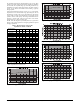
Airflow S etup for Non- communicating Fan Coil
The system can be installed with a standard 2- stage thermostat and
FVM4X fan coil without additional accessories. Select appropriate
unit size on fan coil Easy select board.
Airflow Setup for Non- communicating Furnaces
For installations with non- communicating furnaces, set airflows to
350- 400 cfm/nominal ton in high stage and 70 - 80 percent of high
stage airflow in low stage.
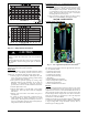
Step 9 — Install Accessories
No refrigeration circuit accessories are required or are available for
installation within the unit. External to the unit, the same
accessories such as support feet, wind baffle etc., available on other
units, can also be used on this line of product. For models utilizing
23 inch x 23 inch base pans, it is recommended to use 5 support
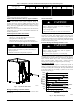
feet in order to fully support unit. See Fig. 8. Refer to the
individual Installation Instructions packaged with kits or
accessories when installing.
A14008
Fig. 8 - Recommended Support Feet Location
(for23x23basepans)
Step 10 — Start- Up
CAUTION
!
UNIT OPERATION AND SAFETY HAZARD
Failure to follow this caution may result in minor personal
injury, equipment damage or improper operation.
Observe the following:
1.Do not overcharge system with refrigerant.
2.Do not operate unit in a vacuum or at negative pressure.
3.Do not disable low pressure transducer or system safety
devices such as discharge thermistor or the high pressure
switch.
4.Dome temperatures may be hot.
5.Discharge thermistor is engaged tight on the discharge tube.