
Installation Manual


5 421 01 5900 02
Specifications subject to change without notice.
Final Tubing Check
IMPORTANT: Check to be certain factory tubing on both indoor
and outdoor unit has not shifted during shipment. Ensure tubes are
not rubbing against each other or any sheet metal. Pay close
attention to feeder tubes, making sure wire ties on feeder tubes are
secure and tight.
Step 7 — Make Electrical Connections
!
WARNING
ELECTRICAL SHOCK HAZARD
Failure to follow this warning could result in personal
injury or death.
Do not supply power to unit with compressor terminal box
cover removed.
Be sure field wiring complies with local and national fire, safety,
and electrical codes, and voltage to system is within limits shown
on unit rating plate. Contact local power company for correction of
improper voltage. See unit rating plate for recommended circuit
protection device.
NOTE: Operation of unit on improper line voltage constitutes
abuse and could affect unit reliability . See unit rating plate. Do not
install unit in system where voltage may fluctuate above or below
permissible limits.
NOTE: Use copper wire only between disconnect switch and unit.
NOTE: Install branch circuit disconnect of adequate size per NEC
to handle unit starting current. Locate disconnect within sight from
and readily accessible from unit, per Section 440- 14 of NEC.
Route Ground and Power Wires
Remove access panel to gain access to unit wiring. Extend wires
from disconnect through power wiring hole provided and into unit
control box.
!
WARNING
ELECTRICAL SHOCK HAZARD
Failure to follow this warning could result in personal injury
or death.
The unit cabinet must have an uninterrupted or unbroken
ground to minimize personal injury if an electrical fault
should occur. The ground may consist of electrical wire or
metal conduit when installed in accordance with existing
electrical codes.
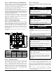
Connec t Ground and Power Wires
Connect ground wire to ground connection in control box for
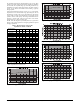
safety. Connect power wiring to contactor as shown in Fig. 5.
A14028
Fig. 5 - Line Power Connections
Observer
®
Control Wiring - Observer Wall
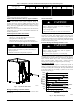
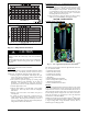
Connect four wires from Observer to communicating furnace / fan
coil with communicating motor capability. Only two wires from
furnace / fan coil DX+ (GR), DX- (YL) are connected to the
outside inverter wiring GR (DX+), YL (DX- ) (see Fig. 6).
Connect C (WT) is recommended if wires are available (see Fig.
6). This will reduce the chance of communication issues. Unused
low voltage wires should be bundled together and terminated with
a wire nut at each end. The end nearest indoor coil should be
connected to C terminal.
IMPORTANT: This system requires the power supplied to the
outdoor unit, and the indoor unit, for the Observer Wall Control to
communicate with the outdoor unit.
A150636
Fig. 6 - Communicating Furnace or Fan Coil Wiring with
Communicating Variable Speed AC
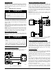
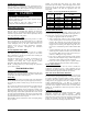
Connect Control Wiring- Non- Communicating
4 wires are required when connecting CVA9, HVA9, TVA9 models
to non- communicating 2- stage thermostats. Use Fig. 7 For
required connections. Unit is configured by factory for Observer
®
communicating control. To wire unit for non - communicating
control, disconnect the DX+ = GN and DX - = YL wires from
green plug and connect appropriate wires to low voltage terminal
block. Use wire nuts to attach thermostat wire to low voltage
choke harness LVCH harness.
General Information
Use 18- 20 solid AWG color- coded, insulated (355C minimum)
wire for low voltage control wires. All wiring must be NEC Class
2 and must be separated from incoming power leads.
Installations using greater than 200 feet of low voltage wiring
should consult the Observer wall control manual for additional
guidelines regarding daisy chaining wiring method and terminating
resistors.
Never route control wiring in parallel to high voltage power wires
when possible as electrical noise may transfer and generate
nuisance fault codes. Where low voltage control and high voltage
wires must cross paths, do so at perpendicular angles to eliminate
transferred noise. If further communication issues exist, consider
using shielded low voltage wires and only connect shielding to C
terminal at end nearest indoor coil.
Use furnace transformer , fan coil transformer, or accessory
transformer for control power requirement of system accessories
external to the OD unit. The outdoor unit has its own transformer
power.