
Installation Manual


421 01 5900 02 2
Specifications subject to change without notice.
!
WARNING
ELECTRICAL HAZARD - HIGH VOLTAGE!
Failure to follow this warning could result in personal injury
or death.
Electrical components may hold charge. DO NOT remove
control box cover for 2 minutes after power has been
removed from unit.
PRIOR TO TOUCHING ELECTRICAL COMPONENTS:
Verify zero (0) voltage at inverter connections shown on
inverter cover.
EXPLOSION HAZARD
Failure to follow this warning could
result in death, serious personal injury,
and/or property damage.
Never use air or gases containing
oxygen for leak testing or operating
refrigerant compressors. Pressurized
mixtures of air or gases containing
oxygen can lead to an explosion.
!
WARNING
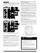
Inverter Cover
IMPORTANT: The inverter cover should NEVER be removed
because there is no reason to remove the inverter cover to access
the inverter . The inverter has limited serviceability. Refer to
Service Manual for details on field replaceable parts. A
replacement cover is provided with a replacement inverter.
INSTALLATION RECOMMENDATIONS
In some cases noise in the living area has been traced to gas
pulsations from improper installation of equipment.
1. Locate unit away from windows, patios, decks, etc. where
unit operation sound may disturb customer.
2. In noise sensitive applications (such as bedrooms), when a
lineset is mounted to ceiling joists or floor joists, the out-
door unit must be located at least 10 ft (3.05 m) away. If
this is not possible, create a line set configuration with
enough bends to provide 10 ft (3.05 m) of total line set
length outside the dwelling
3. Ensure that vapor and liquid tube diameters are appropriate
for unit capacity.
4. Run refrigerant tubes as directly as possible by avoiding un-
necessary turns and bends.
5. Leave some slack between structure and unit to absorb vi-
bration.
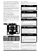
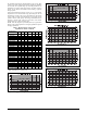
6. When passing refrigerant tubes through the wall, seal open-
ing with RTV or other pliable silicon- based caulk (see Fig.
1).
7. Avoid direct tubing contact with water pipes, duct work,
floor joists, wall studs, floors, and walls.
8. Do not suspend refrigerant tubing from joists and studs with
a rigid wire or strap which comes in direct contact with tub-
ing (see Fig. 1).
9. Ensure that tubing insulation is pliable and completely sur-
rounds vapor tube.
10. When necessary, use hanger straps which are 1 in. wide and
conform to shape of tubing insulation. (See Fig. 1.)
11. Isolate hanger straps from insulation by using metal sleeves
bent to conform to shape of insulation.
EQUIPMENT DAMAGE HAZARD
Failure to follow this caution may result in equipment damage.
If proper lineset routing techniques are not followed, variable
speed systems can be susceptible to lineset transmitted noise
inside the dwelling and, in extreme cases, tubing breakage.
CAUTION
!
A07588
Fig. 1 - Connecting Tubing Installation
The outdoor unit contains the correct amount of refrigerant charge
for operation with AHRI rated indoor units when connected by 15
ft (4.57 m) of field- supplied or factory accessory tubing.
See Step 12 on page 7 for proper charging procedure.
IMPORTANT: Liquid- line size is 3/8- in. OD for all CVA9,
HVA9, TVA9 applications. The maximum allowable equivalent
line set length is 100 ft. (30.5 m).
IMPORTANT: Always install the factory- supplied liquid- line
filter drier. Obtain replacement filter driers from your distributor or
branch.
INSTALLATION
Specifications for this unit in residential new construction market
require the outdoor unit, indoor unit (including metering device),
refrigerant tubing sets, and filter drier listed in pre- sale literature.
There can be no deviation. Consult the Service Manual – Air
Conditioners and Heat Pumps Using R- 410A Refrigerant to obtain
required unit changes for specific applications and for R- 22
retrofit.
Step 1 — Check Equipment and Job Site
Unpack Unit
Move to final location. Remove carton taking care not to damage
unit.
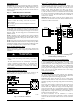
Inspect Equipment
File claim with shipping company prior to installation if shipment
is damaged or incomplete. Locate unit rating plate on unit corner
panel. It contains information needed to properly install unit.
Check rating plate to be sure unit matches job specifications.