
Installation Manual


421 01 5900 02 10
Specifications subject to change without notice.
Variable Speed Compressor
This unit contains a variable speed rotary compressor that has a
wide operating range. It operates on a variable 3 phase sine wave
provided by the inverter. This compressor can only be operated by
the specific inverter supplied with the unit.
EQUIPMENT DAMAGE HAZARD
Failure to follow this caution may result in equipment damage
and/or improper operation.
Do not attempt to apply line voltage directly to the
compressor. This will destroy the compressor.
CAUTION
!
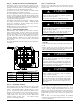
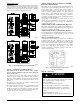
Field control Connections
For communicating operation use the communication Observer
®
plug only. Only two wires, DX+, DX- (GN,YL), are required. If
necessary, connect C for additional grounding (see Fig. 6). If using
standard 2- stage thermostat, connect discrete inputs (R,C,Y2,Y1)
for 2 - stage control in cooling modes.
Pressure Transducer (SPT)
A 5 VDC output low pressure transducer that provides a 0- 5 VDC
data for interpretation by the control board for a 0 to 200 psig
range of pressure at the suction tube. This interpreted pressure data
is then intelligently used by the AOC control board for low
pressure cut- out, loss of charge management, compressor
protection, oil circulation management, and lubrication
management.
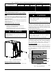
Pressure Equalizer Valve (PEV)
At the end of every compressor operation (after the 3.5 minute
Time Guard period), the equalizer valve opens for 150 seconds
plus an additional 15 seconds of protection before allowing the
compressor to start ramping up.
The PEV is located next to the suction and discharge of the
compressor. The function of this valve is to prevent the
compressor from starting with a high refrigerant pressure
differential, thus helping the reliability of the compressor.
NOTE: A hissing sound may be heard during the equalization
process. This is normal.
TROUBLESHOOTING
Systems Communication Failure
If communication is lost with the Observer Wall Control, the green
LED will go out. Check the wiring to the Observer Wall Control
and the indoor and outdoor units and power.
Model Plug
Each control board contains a model plug. The correct model plug
must be installed for the system to operate properly (see Table 3).
The model plug is used to identify the type and size of unit to the
control.
On new units, the model and serial numbers are inputted into the
AOC board’s memory at the factory. If a model plug is lost or
missing at initial installation, the unit will operate according to the
information input at the factory and the appropriate error code will
flash temporarily. A FAST Parts replacement AOC board contains
no model and serial information. If the factory control board fails,
the model plug must be transferred from the original board to the
replacement board for the unit to operate.
When installing AC unit with older fan coils, a model plug change
may be required.
NOTE: The model p lug takes priority over factory model
information input at the factory. If the model plug is removed after
initial power up, the unit will operate according to the last valid
model plug installed, and flash the appropriate fault code
temporarily.
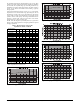
Table 3 – Factory Supplied Model Plug Information
CVA9, HVA9,
T
V
A
9
FAST PART
NUMBER
PIN RESISTANCE
(K- OHMS)
1- 4 (R1) 2- 3 (R2)
24 1184942 18K 91K
25 1188023 18K 5.1K
36 1184944 18K 150K
37 1188024 18K 18K
48 1184946 18K 220K
49 1188025 18K 33K
60 1184948 18K 360K
Pressure Switch Protection
The outdoor unit is equipped with high pressure switch. If the
control senses the opening of a high pressure switch (open 600+/- 5
psig, close 470+/- 10 psig @77_F), it will respond as follows:
1. Display the appropriate fault code (see Table 6).
2. After a 6 minute delay, if there is a call for cooling and HPS
is reset, the PEV opens for 150 seconds to equalize system
pressures. The compressor and fan will then ramp to the
next lower stage of operation until demand is satisfied. The
staging down and resetting to the highest stage will end af-
ter 2 hours of accumulated operation without further HPS
trips.
3. A system malfunction will occur after repeated HPS faults
and the stages has reached the lowest level. This could take
five consecutive HPS trips if the first occurred in stage 5
demand or 1 HPS trip if in stage 1 demand.
4. In the event of a high - pressure switch trip or high - pressure
lockout, check the refrigerant charge, outdoor fan operation,
and outdoor coil (in cooling) for airflow restrictions.
5. In the event of a low- pressure trip or low- pressure lockout,
check the refrigerant charge and indoor airflow (cooling).
Brown- Out Protection
If the line voltage is less than 187V for at least 4 seconds, the
Compressor and OD fan goes to 0 rpm. Compressor and fan
operation are not allowed until voltage is a minimum of 190V. The
control will flash the appropriate fault code (see Table 6).
230V Line (Power Disconnect) Detection
The control board senses the presence of absence of 230V through
inverter feedback. Voltage should present at all times when system
is in service regardless if system is running or standby. If there is
no 230V at the inverter when the indoor unit is powered with a
cooling demand, the appropriate fault code is displayed on Wall
Control (communicating only – see Table 6). If system is
configured with conventional thermostat (non- communicating), no
fault code will be displayed on AOC board, nor will any status
LEDs be lit. Use multimeter to check for the presence of 230V in
this situation.
Temperature Thermistors
Thermistors are electronic devices which sense temperature. As the
temperature increases, the resistance decreases. 10Kohm
thermistors are used to sense outdoor air temperature (OAT), coil
temperature (OCT) and the suction line temperature (OST) located
between the reversing valve and the accumulator. A 50Kohm
thermistor is used to sense discharge temperature (ODT).