
Installation Manual


56
Specifications are subject to change without notice.
441 01 3500 00
b. After waiting 10 seconds the furnace control CPU
turns the hot surface igniter ON for 15 seconds, then
OFF.
c. The furnace control CPU then turns the blower motor
BLWM on at mid--range airflow for 15 seconds, then
OFF.
d. After shutting the blower motor OFF the furnace con-
trol CPU switches the inducer to low--heat speed for
10 seconds, then OFF.
NOTE: The EAC terminals are energized when the blower is
operating.
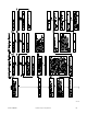
After the component test is completed, 1 or more status codes
(heartbeat, 2+5) will flash. See component test section or Service
Label (Fig. 48) for explanation of status codes.
NOTE: To repeat component test, turn setup switch SW1--6 to
OFF and then back ON.
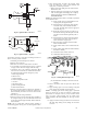
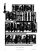
Wiring
Diagram
Refer to wiring diagram Fig. 49.
Tr
oubleshooting
Refer to the service label. (See Fig. 48—Service Label.)
The Troubleshooting Guide (See Fig. 54.) can be a useful tool in
isolating furnace operation problems. Beginning with the word
“Start,” answer each question and follow the appropriate arrow to
the next item.
The Guide will help to identify the problem or failed component.
After replacing any component, verify correct operation
sequence.
A more detailed Troubleshooting Guide is available from your
distributor.