
Specifications
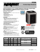


PRODUCT SPECIFICATIONS Split System Air Conditioner: HVA9
421 51 5800 02 4
Specifications subject to change without notice.
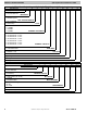
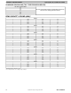
COOLING CAPACITY LOSS TABLE
Nominal
Size
(Btuh)
Line OD (in.)
HVA9 Cooling Capacity Loss (%)
Total Equivalent Line Length (ft)
25 50 75 80 100
24
5/8 0.5 1.2 1.8 1.9 2.4
3/4 0.1 0.4 0.6 0.7 0.8
25
5/8 0.5 1.2 1.8 1.9 2.4
3/4 0.1 0.4 0.6 0.7 0.8
7/8 0.0 0.1 0.3 0.3 0.4
36
37
5/8 1.1 2.4 3.7 4.0 5.0
3/4 0.3 0.8 1.3 1.4 1.8
7/8 0.0 0.3 0.5 0.6 0.8
48
49
3/4 0.7 1.6 2.4 2.6 3.2
7/8 0.3 0.7 1.1 1.2 1.6
1 1/8 0.0 0.1 0.2 0.3 0.4
60
3/4 1.0 2.3 3.5 3.8 4.8
7/8 0.4 1.0 1.7 1.8 2.3
1 1/8 0.0 0.1 0.3 0.4 0.5
Rating Line Size in BOLD
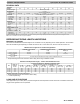
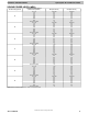
MIN/MAX AIRFLOW TABLES
The indoor airflow delivered by this system varies significantly based on outdoor temperature, indoor unit combination, and
system demand. The airflows on these tables are for duct design considerations. Duct systems capable of these ranges will
ensure the system will deliver full capacity at all outdoor temperatures.
Minimum and maximum airflows can be adjusted from these numbers in the Observer® Control Setup screen.
Cooling - Comfort Mode
Minimum Cooling
(Dehum or Zoning)
Size Max Stage 5 Airflow Max Stage 1 Airflow
2-Ton 739 300 300
3-Ton 990 300 300
4-Ton 1389 542 457
5-Ton 1600 700 600
Cooling - Efficiency Mode
Size Max Stage 5 Airflow Max Stage 1 Airflow
2-Ton 825 585
3-Ton 1050 600
4-Ton 1400 875
5-Ton 1800 975
Cooling Max Mode
Size Max Stage 5 Airflow Max Stage 1 Airflow
2-Ton (24) 850 585
2-Ton (25) (550 cfm/ delivered ton)* 1350 510
3-Ton 1200 600
4-Ton 1600 875
4-Ton-49 1450 875
5-Ton 2000 975
LEGEND::
Max Capacity Airflow - Stage 5 airflow varies depending on conditions. This is the highest airflow the system will attempt to deliver in this particular mode. Duct
work for non-zoned systems should be sized for this airflow to ensure the system can deliver full capacity when needed. Improper duct design may result in
excessive airflow noise and/or cutback occurrences at max airflow conditions.
Highest Min. Capacity Airflow - Stage 1 airflow also varies depending on conditions. In zoned systems, each zone must be capable of delivering this airflow for
the system to deliver full capacity into the zone. Otherwise, airflow may be diverted to other zones or cutback may occur.
Min Cooling (Dehum or Zoning) - Lowest airflow the system will deliver. May operate down to this airflow in dehumidification mode or in zoning applications
where ductwork restrictions have caused the blower to cut-back.
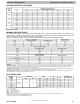
ELECTRICAL DATA
UNIT SIZE-
VOLTAGE,
SERIES
V/PH
OPER VOLTS* COMPR FAN
MCA
MAX FUSE ** or
CKT BRK AMPS
MAX MIN LRA RLA FLA
24
208/230
-1-60
253 197
N/A 10.3 0.58 13.5 20
25 N/A 17.7 1.20 23.6 40
36 N/A 18.4 1.20 24.2 40
37 N/A 19.6 1.20 26.0 40
48 N/A 20.9 1.20 27.3 40
49 N/A 19.6 1.40 26.0 40
60 N/A 30.9 1.40 40.0 60
* Permissible limits of the voltage range at which the unit will operate satisfactorily
** Time-Delay fuse.
FLA - Full Load Amps
LRA - Locked Rotor Amps
MCA - Minimum Circuit Amps
RLA - Rated Load Amps
NOTE: Control circuit is 24-V on all units and requires external power source. Copper wire must be used from service disconnect to unit.
All motors/compressors contain internal overload protection.
Complies with 2010 requirements of ASHRAE Standards 90.1