
Specifications


PRODUCT SPECIFICATIONS Fan Coils: FCM4X
496 51 4202 02 9
Specifications are subject to change without notice.
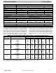
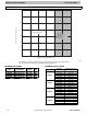
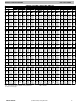
AIR DELIVERY PERFORMANCE CORRECTION COMPONENT PRESSURE DROP (in wc)
AT INDICATED AIRFLOW (DRY T O WET COIL)
MODEL
FCM4X
CFM
600 700 800 900 1000 1100 1200 1300 1400 1500 1600
24 0.012 0.016 0.022 0.028 0.034 0.040 0.049 — — — —
36 — 0.026 0.034 0.042 0.052 0.063 0.075 0.083 0.091 0.098 0.110
48 — 0.006 0.008 0.010 0.012 0.015 0.017 0.020 0.023 0.027 0.030
CFM
1100 1200 1300 1400 1500 1600 1700 1800 1900 2000 2100
60 0.013 0.016 0.018 0.020 0.023 0.027 0.030 0.034 0.039 0.044 0.048
NOTE: Subtract the above pressure drop corrections from unit airflow data when that component or condition is used. The remaining external static pressure
will be available for the duct system.
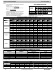
UNITS WITHOUT ELECTRIC HEAT
MODEL
FCM4X
VOLTS- PHASE FLA MIN CKT AMPS
BRANCH CIRCUIT
Min Wire Size Awg* Fuse/Ckt Bkr Amps
24 208/230- 1 4.3 5.4 14 15
36 208/230- 1 4.3 5.4 14 15
48 208/230- 1 4.3 5.4 14 15
60 208/230- 1 6.8 8.5 14 15
* Use copper wire only to connect unit. If other than uncoated (non- plated) 75 C ambient, copper wire (solid wire for 10 AWG and smaller, stranded wire
for larger than 10 AWG) is used consult applicable tables of the National Electric Code (ANSI/NFPA 70).
NOTE: If branch circuit wire length exceeds 100 ft / 30.5 m, consult NEC 210- 19a to determine maximum wire length. Use 2% voltage drop.
FLA — Full Load Amps
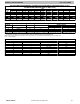
ELECTRIC HEATER INTERNAL PROTECTION
HEATER kW PHASE FUSES QTY / SIZE CKT BKR QTY / SIZE*
5 1 — 1/60
8 1 — 1/60
9 1/3 — —
15 1 2/30, 2/60 2/60
15 3 — —
18 3 — —
20 1 4/60 2/60
24 3/1 6/60 —
30 3/1 6/60 —
* All circuit breakers are 2 pole.