
Installation Manual


INST ALLATION INSTRUCTIONS Fan Coils: FCM4X
8 496 01 4201 04
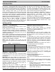
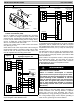
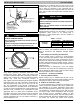
Figure 8 T ransformer Connections
230
C
208
SECONDARY
PRIMARY
BLACK
YELLOW
RED
BROWN
A94067
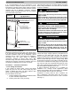
B. 24- V Control System Connections to Unit
Printed- Circuit Board (PCB)
Use No. 18 AWG color- coded, insulated (35C minimum)
wires to make low- voltage connections between Wall
Control and unit. If W all Control is located more than 100
ft. from unit (as measured along the low- voltage wires),
use No. 16 AWG color- coded, insulated (35C minimum)
wires or in accordance with local codes.
Connect low- voltage leads to Wall Control and outdoor
unit. (See Fig. 9 or 10.)
NOTE: Where local codes require Wall Control wiring be
routed through conduit or raceways, splices can be made
inside fan coil unit. All wiring must be NEC Class l and
must be separated from incoming power leads.
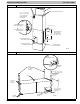
Figure 9
Fan Coil Wiring with Non- Communicat-
ing Single- Stage AC / HP
A07119
Humidifier
Outdoor Air Thermistor
(if used)
OAT
Non- communicating AC / HP
24vac
C
C
Y
W
G
WR
R
C
HUM
O
COM
OPN
CLS
DX+
DX-
C
R
DX+
DX-
C
R
Y
O
Wall Control Fan Control
NOTE: Two- stage non- communicating AC and HP wiring
require daughter board NAXA00101DB.
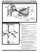
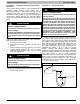
Figure 10
Fan Coil Wiring Communicating AC/HP
OAT
24vac
C
CLS
OPN
COM
DX+
DX-
C
R
DX+
DX-
C
R
DX+
DX-
C
R
HUM
COYW
GR
Wall Control
Fan Control
Communication
AC / HP
Humidifier
C. Manufactured Housing
In manufactured housing applications, the Code of Federal
Regulations, Title 24, Chapter XX, Part 3280.714 requires
that supplemental electric heat be locked out at outdoor
temperatures above 40F(4.4C), except for a heat pump
defrost cycle.
The Wall Control with an outdoor air temperature sensor
can be used to lockout supplemental heat above 40F
(4.4C) except for heat pump defrost cycle. Refer to Wall
Control Instructions.
NOTE: Outdoor air temperature sensor is factory installed
on communicating single- and two- stage AC and HP
units. For non- communicating outdoor units, install the
TSTATXXSEN01B outdoor air temperature sensor.
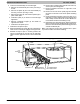
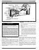
D. Ground Connections
!
WARNING
ELECTRICAL SHOCK HAZARD
Failure to establish uninterrupted or unbroken
ground could result in personal injury and/or death.
The ca bine t must have an uninterr upt e d or unbrok e n
ground according to NEC, ANSI/NFP A 70 and local
code s to minim iz e pers ona l injury if an elec t r ic a l fault
should oc c ur. The ground may consis t of elec tr ical
wire or me ta l conduit when insta lle d in accordance
with exis t ing elec t r ic a l code s . (Se e Ground/C onduit
Note below.)
NOTE: Use UL listed conduit and connectors to connect
supply wire(s) to unit and obtain proper grounding. If
conduit connection uses reducing washers, a separate
ground wire must be used. Grounding may also be
accomplished by using grounding lug provided in control
box. Using multiple supply circuits requires grounding of
each circuit to ground lugs on unit and heaters.