
Installation Manual


INST ALLATION INSTRUCTIONS Fan Coils: FCM4X
2 496 01 4201 04
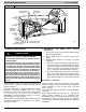
INTRODUCTION
Model FCM4X fan coils are designed to be installed with
the Observert Communicating Wall Control. The FCM4X
fan coils will provide airflow at a rate commanded by the
W all Control. The nominal airflow/ton rate is 350 CFM/ton.
The Wall Control will modify the commanded airflow under
certain operating modes. Refer to the Wall Control
literature for further system control details. This fan coil will
not respond to commands from a common thermostat
except under certain emergency situations explained in
this document. The instructions contained herein provide
guidance to successfully install this fan coil.
Model FCM4X fan coil units are designed for flexibility and
can be used for upflow , horizontal, or downflow
applications. These units are designed specifically for
R- 410A refrigerant and must be used only with R- 410A
refrigerant air conditioners and heat pumps as shipped.
These units are designed to meet cabinet air leakage of
less than 2% at 0.5 inches W.C. and cabinet air leakage
less than 1.4% at 0.5 inches W .C. when tested in
accordance with ASHRAE 193 standard. Because of this,
units need special attention in the condensate pan and
drain connection area and when brazing tubing.
These units are available for application in systems of
24,000 through 60,000 Btuh nominal cooling capacities.
Factory- authorized, field- installed electric heater
packages are available in 5 through 30 kW. See
Specifications for available accessory kits.
If the unit is located in an area of high humidity, nuisance
sweating of the casing may occur. On these installations a
wrap of 2 (51 mm) fiberglass insulation with a vapor
barrier is recommended.
INSTALLATION
Procedure 1. — Check Equipment
Unpack unit and move to final location. Remove carton
taking care not to damage unit.
Inspect equipment for damage prior to installation. File
claim with shipping company if shipment is damaged or
incomplete. Locate unit rating plate which contains proper
installation information. Check rating plate to be sure unit
matches job specifications.
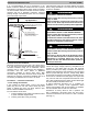
Refer to Table 1. Install the fan coil with the accompanying
kit to ensure compliance with low leak requirements of less
than 2% cabinet leakage rate at 0.5 inches W.C. and 1.4%
cabinet leakage rate at 0.5 inches W.C. when tested in
accordance with ASHRAE 193 standard.
NOTE: Units that require a kit to meet low leak
requirements have a gasket kit automatically included with
shipment.
Table 1
– Gasket Kit Requirement
Unit Size
Kit Needed?
024 Yes
036 Yes
048 Yes
060 Yes
Procedure 2. — Mount Fan Coil
FCM4X unit can stand or lie on floor , or hang from ceiling
or wall. Allow space for wiring, piping, proper trapping and
servicing unit.
IMPORTANT: When unit is installed over a finished ceiling
and/or living area, building codes may require and it is
recommended by the factory, a field- supplied secondary
condensate pan to be installed under the entire unit. Some
localities may allow the alterative of running a separate,
secondary condensate line. Consult local codes for
additional restrictions or precautions.
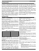
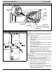
FCM4X fan coils can be installed for upflow and
horizontal- left applications as factory shipped. (See
Figures 1, 2 and 3.) FCM4X units can be installed for
horizontal- right applications with field modifications.
FCM4X units may be converted for downflow applications
using factory- authorized accessory kits.
NOTE: To ensure proper drainage for horizontal
installations, unit must be installed so it is within 1/8” / 3.18
mm level of the length and width of unit.
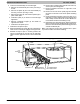
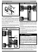
A. Modular Units
The FCM4X60 Fan Coil are 2- piece modular units.
Modular construction allows installer to disassemble unit
into 2 components, coil box and blower box, for ease of
installation.
To disassemble unit, remove rear corner brackets by
removing 2 screws which secure brackets. Remove either
2 screws in each front corner of coil box, or 2 screws in
blower box. (See Fig. 4.) Do not remove all 4 screws in
each corner. Sections may now be separated by lifting top
section from lower section.
To reassemble, reverse above procedure. Be certain to
reinstall all fasteners when reassembling.
B. Upflow Installation
If return air is to be ducted through a floor, set unit on floor
over opening and use 1/8” / 3.18 mm to 1/4” / 6.35 mm
thick fireproof resilient gasket between duct, unit, and
floor.
Side return is a field option on slope coil models. Cut
opening per dimensions. (See Fig. 1.) A field- supplied
bottom closure is required.
All return- air must pass through the coil.
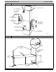
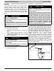
C. Horizontal Installations
Units must not be installed with access panels facing up or
down.
Be sure installation complies with all applicable building
codes that may require installation of a secondary
condensate pan.
1. Arrange support for unit by setting it in or above
secondary condensate pan.
2. When suspending unit from ceiling dimples in casing
indicate proper location of screws for mounting metal
support straps. (See Fig. 2.)