
Installation Manual

INST ALLATION INSTRUCTIONS Fan Coils: FCM4X
496 01 4201 04 15
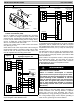
system efficiency. Refer to Wall Control literature for
further system control details.
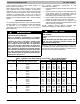
Airflow during electric heater operation must be greater
than a minimum level for safe operation. If Wall Control
instructs fan coil to turn on electric heat and the requested
airflow is less than the minimum value required for safe
operation of installed heater, the fan coil control will
override requested value with the value shown in Table 2,
FCM4X Fan Coil Airflow Delivery Chart - Electric Heating
Modes.
CARE AND MAINTENANCE
For continuing high performance, and to minimize possible
equipment failure, it is essential that periodic maintenance
be performed on this equipment. The only required
maintenance that may be performed by the consumer is
filter maintenance.
!
WARNING
ELECTRICAL SHOCK HAZARD
Failure to establish uninterrupted or unbroken
ground could result in personal injury and/or death.
Disconnect all power to unit before servicing field
wires or removing control package. The disconnect
(when used) on access panel does not disconnec t
power to the line side of disc onne c t, but does allow
safe service to all other parts of unit. If unit does not
hav e a disconne c t , disre ga r d the for e going. Instead,
make sure that a disconnecting means is within sight
from, and is readily accessible from, the unit. Discon-
nect all electrical power to unit before performing any
maintenance or service on it.
The minimum maintenance requirements for this
equipment are as follows:
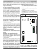
1. Inspect and clean or replace air filter each month or as
required.
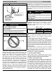
2. Inspect cooling coil, drain pan, and condensate drain
each cooling season for cleanliness. Clean as
necessary. An inspection port is provided on all A- coil
delta plates. Remove plastic plug to inspect.
3. Inspect blower motor and wheel for cleanliness each
heating and cooling season. Clean as necessary.
4. Inspect electrical connections for tightness and
controls for proper operation each heating and cooling
season. Service as necessary.
Consult Technical Service Manual available from
equipment distributor for maintenance procedures.
!
CAUTION
CUT HAZARD
Failure to follow this caution may result in personal
injury.
Sheet metal parts may have sharp edges or burrs. Use
ca r e a nd wear appr opr iate prot e c tive clothing and
glove s when handling part s
Using the Owner’s/User Manual furnished in outdoor unit,
the installing technician should explain system operation to
the consumer with particular emphasis on indoor fan coil
operation sounds and filter maintenance.
Table 2
– FCM4X Fan Coil Airflow Delivery Chart (CFM) — Electric Heating Models
MODEL FCM4X OUTDOOR UNIT CAPACITY BTUH
ELECTRIC HEATER kW RANGE
5 7-9 10 15 20 24- 25 30
24
EMERGENCY
18,000
24,000
30,000
36,000
625
625
650
800
975
625
625
725
875
975
675
675
775
875
975
775
—
900
925
1025
950
—
—
1125
1125
—
—
—
—
—
—
—
—
—
—
36
EMERGENCY
24,000
30,000
36,000
42,000
675
675
800
975
1125
700
875
875
975
1125
775
875
875
1025
1125
850
1100
1100
1150
1150
1050
1150
1150
1250
1350
—
—
—
—
—
—
—
—
—
—
48
EMERGENCY
30,000
36,000
42,000
48,000
675
800
975
1125
1305
700
875
975
1125
1305
775
875
1025
1125
1305
850
1100
1150
1150
1305
1050
1150
1250
1250
1350
1400
—
—
—
1500
1425
—
—
—
1600
60
EMERGENCY
36,000
42,000
48,000
60,000
1050
1050
1125
1300
1625
1050
1050
1125
1300
1625
1050
1100
1150
1300
1625
1050
1350
1350
1350
1625
1125
1350
1350
1500
1750
1750
—
—
1750
1750
1750
—
—
1750
1750