
Installation Manual

INST ALLATION INSTRUCTIONS Fan Coils: FCM4X
12 496 01 4201 04
with Wall Control are successful, COMM LED will be lit
and held on. At the same time, amber STATUS LED will
be lit and held continuously on until a request for operating
mode is received. The STATUS LED will be on any time
fan coil is in idle mode. If, at any time, communications are
not successful for a period exceeding 2 minutes, fan coil
control will only allow emergency heating or cooling
operation using a common thermostat, a
non- communicating outdoor unit and the R, C, Y, O, W
outdoor unit terminal strip connections and will display
Status Code 16, System Communication Fault,on
amber STATUS LED. No further fan coil troubleshooting
information will be available at Wall Control until
communications are re- established.
If COMM LED does not light within proper time period and
Status Code is not displayed:
1. Check system transformer high and low voltage to be
sure the system is powered.
2. Check fuse on fan coil control to be sure it is not blown.
If fuse is open, check system wiring before replacing it
to be sure a short does not cause a failure of
replacement fuse.
If COMM LED does not light within proper time period and
Status Code is displayed:
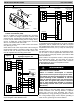
Check system wiring to be sure Wall Control is powered
and connections are made DX+ to DX+, DX- to DX- , etc.
and wiring is not shorted. Mis- wiring or shorting of the
DX+DX- CR communications wiring will not allow
successful communications.
NOTE: Shorting or mis- wiring low voltage system wiring
will not cause damage to fan coil control or Wall Control
but may cause low voltage fuse to open.
C. ECM Motor Troubleshooting
The ECM motor used in this product consists of two parts:
the Control Module and the motor winding section. Do not
assume motor or module is defective if it will not start. Use
the designed- in LED information aids and follow
troubleshooting steps described below before replacing
motor Control Module or entire motor . Motor Control
Module is available as a replacement part.
VERIFY MOTOR WINDING SECTION:
!
WARNING
ELECTRICAL SHOCK HAZARD
Failure to follow this warning could result in personal
injury possible equipment damage.
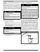
After disconnecting po wer from the ECM motor, wait
at least 5 minutes before removing the control sec-
tion. Internal capacitors require time to discharge.
Before proceeding to replace a motor Control Module:
1. Check motor winding section to be sure it is functional.
2. Remove motor Control Module section and unplug
winding plug. Motor shaft should turn freely,
resistance between any two motor leads should be
similar and resistance between any motor lead and
unpainted motor end should exceed 100,000 ohms.
3. Failing any of these tests, entire ECM motor must be
replaced.
4. Passing all of the tests, motor Control Module alone
can be replaced.
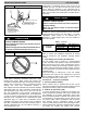
MOTOR TURNS SLOWLY:
1. Low static pressure loading of blower while access
panel is removed will cause blower to run slowly.
Particularly at low airflow requests. This is normal, do
not assume a fault exists.
NOTE: Blower motor faults will not cause a lockout of
blower operation. Fan coil control will attempt to run the
blower motor as long as W all Control maintains a demand
for airflow. Fan coil control will not operate electric heaters
while a fault condition exists. The fan coil control
communicates with the motor at least once every 5
seconds, even when the motor is idle. If, during operation,
the fan coil control does not communicate with the motor
for more than 25 seconds, the motor will shut itself down
and wait for communications to be reestablished.
D. Using Motor LED in Troubleshooting
The MOTOR LED is connected to the blower motor
communication line and works with the fan coil control
microprocessor and the STATUS LED to provide fan coil
operation and troubleshooting information. When the
motor is commanded to operate, the MOTOR LED will be
turned on and will flash each time instructions are sent to
the motor . When the motor is commanded to stop, the
MOTOR LED will be turned off.
If the MOTOR LED is lit, flashing and the motor is running
or if the MOTOR LED is off and the motor is stopped,
operation is normal and no motor fault exists.
If the MOTOR LED is lit, flashing and the motor does not
run, or if the MOTOR LED is off and the motor is running,
check the STATUS LED for the Status Code. Refer to the
troubleshooting instructions for the indicated Status Code
in Section E, Fan Coil Troubleshooting.
E. Fan Coil Troubleshooting
Fan coil faults indicated by flashing codes on the amber
system STATUS LED can be resolved using
troubleshooting information provided below. Codes are
listed in order of their priority, highest to lowest. Though
multiple faults can exist at any time, only the highest
priority code will be displayed on STATUS LED. Clearing
the indicated fault when multiple faults exist will cause the
next highest priority Status Code to be flashed. All existing
faults, as well as a fault history, can be viewed at W all
Control.
STATUS CODE 45, CONTROL BOARD TEST FAULT:
Fan coil control has failed internal start- up tests and must
be replaced. No other service procedure will correct.
STATUS CODE 37, HEATER OUTPUT SENSED “ON”
WHEN NOT ENERGIZED:
Fan coil control is provided with circuitry to detect
presence of a 24VAC signal on Electric Heater stage 1
and stage 2 outputs. If fan coil control detects a 24VAC
signal on either heater stage output and it is not supplying
signal, Status Code 37 will be displayed on STATUS LED.
Fan coil control will turn off output and command blower
motor to supply an airflow determined to be safe for
current operation mode with electric heaters energized.
To find the fault: