
Installation Manual


INST ALLATION INSTRUCTIONS Fan Coils: FCM4X
10 496 01 4201 04
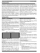
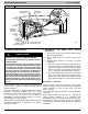
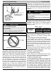
Figure 12 Condensate Trap and Unit
FILTER ACCESS PANEL
SECONDARY DRAIN WITH
PRIMARY TRAP REQUIRED
APPROPRIATE TRAP REQUIRED
(USE FACTORY KIT OR
FIELD- SUPPLIED TRAP)
(USE FACTORY KIT OR
FIELD- SUPPLIED TRAP OF
SUFFICIENT DEPTH.
STANDARD P- TRAPS ARE
NOT SUFFICIENT. SEE
FIGURE OF RECOMMENDED
CONDENSATE TRAP)
!
CAUTION
PRODUCT DAMAGE HAZARD
Failure to follow this caution may result in product or
property damage.
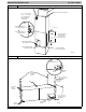
Shallow running traps are inadequate and DO NOT al-
low proper condensate drainage. (See Fig. 13.)
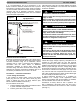
Figure 13 Insufficient Condensate Trap
DO NOT USE SHALLOW RUNNING TRAPS!
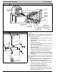
NOTE: When connecting condensate drain lines, avoid
blocking filter access panel. Prime both primary and
secondary condensate traps after connecting to drain pan.
NOTE: If unit is located in or above a living space where
damage may result from condensate overflow, a
field- supplied external condensate pan should be installed
underneath entire unit, and a secondary condensate line
(with appropriate trap) should be run from unit into the
pan. Any condensate in this external condensate pan
should be drained to a noticeable place. As an alternative
to using an external condensate pan, some localities may
allow the use of a separate 3/4- in. condensate line (with
appropriate trap) to a place where condensate will be
noticeable. The owner of the structure must be informed
that when condensate flows from the secondary drain or
external condensate pan, the unit requires servicing, or
water damage will occur .
Install traps in condensate lines as close to the coil as
possible. (See Fig. 12.) Make sure that the outlet of each
trap is below its connection to the condensate pan to
prevent condensate from overflowing drain pan. Prime all
traps, test for leaks, and insulate traps if located above a
living area.
!
CAUTION
PRODUCT DAMAGE HAZARD
Failure to follow this caution may result in product or
property damage.
Never run unit without a filter or with filter access
door removed.
IMPORTANT: Factory authorized filters must be used when
locating the filter inside the unit. (See Table 1.) For those
applications where access to an internal filter is
impractical, a field- supplied filter must be installed in
return duct system.
Table 1
– Filter Kits
FILTER KIT
(12 PACK)
PART NUMBER SIZE USED WITH
EBAC01FKM 24
EBAC01FKL 36, 48
EBAC01FKX 60
Procedure 7. — Unit Start- Up
Refer to outdoor unit Installation Instructions for system
start- up instructions and refrigerant charging method
details.
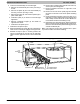
A. Low- Voltage Circuit Fusing and Reference
The low- voltage circuit is fused by a board- mounted
3- amp. automotive fuse placed in series with transformer
SEC1 and R circuit. The C circuit of transformer circuit is
referenced to chassis ground through a printed circuit run
at SEC2 and metal PC board mounting eyelets. Check to
be sure PC Board is mounted securely using both factory
installed screws.
NOTE: Mis- wiring or shorting any of the low voltage
connections may cause the low voltage fuse to open but
will not damage the W all Control or fan coil control. Simply
rewire and replace fuse to correct fault.
Procedure 8. — Accessory Installation
A. Accessory Electric Heaters
Electric heaters may be installed with the fan coil per
instructions supplied with electric heater package. See unit
rating plate for factory- approved electric heater kits.
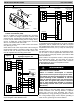
B. Outdoor Air Thermistor (OAT)
A 2- screw terminal strip is provided for connection of an
outdoor temperature thermistor. This strip is marked OAT.
The installation of an outdoor temperature sensor using
the fan coil OAT terminals is optional. If the outdoor unit is
not equipped for communications, fan coil OAT input can
be used to supply outdoor temperature data for system
level functions and for temperature display on W all
Control. Communicating outdoor units are shipped with a
factory installed OAT. This factory installed OAT is used for
all outdoor unit specific and system level functions