
EHK Installation Manual


482 01 2226 05
6
Specifications are subject to change without notice
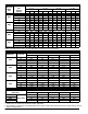
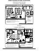
D. FAN SPEED SELECTION
FSM, FSU, EBP, EBX, EBXX & EBW Motor Speed
Selection
1. Speed tap selection is done at fan relay. To change motor
speeds, disconnect fan lead on relay and replace with mo-
tor speed tap desired. Save insulating cap and place on
motor lead that was removed from relay. (See Figure 15)
Refer to table below for further clarification of speed tap
selections.
Motor Speed Tap Wire Color
Common Yellow
High Black
Medium Blue (Factory Selected)
Low
Red
(Blue on 2 speed models)
IMPORTANT!
For FEM Motor Speed Selection, refer to
installation instructions of the FEM fan coil.
For FVM, Variable Motor Speed Selection, refer
to installation instructions of the FVM fan coil.
For EBV Motor Speed Selection, refer to
installation instructions of the EBV fan coil.
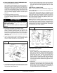
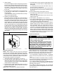
CONVERSION OF CIRCUIT BREAKER FOR
DOWNFLOW APPLICATIONS
1. Tag and disconnect factory wiring from terminals on circuit
breaker(s).
2. Pull white plastic release tab on the bottom of circuit break-
er straight out to release circuit breaker from bracket. (See
Figure 16)
3. Remove quick connect adapters from factory side of
breaker(s). Reinstall adapters on other end of breakers(s).
Be sure adapter is located between lug screw and plate.
Torque lug screw to 30−in−.lb.
4. Rotate breaker 180 degrees from its original position and
reinstall in bracket. Slide breaker slot into sheet metal tab and
snap breaker into place. Make sure both tabs engage break-
er. Reconnect wiring on opposite end. Make sure wires are
positioned as before.
5. Remount circuit breaker bracket into unit so that the switch
will be in UP position when ON.
ATTACH WIRING DIAGRAM AND RATING LABEL
Attach heater rating label included with kit over existing elec-
trical information label located on front access panel of fan
coil. (See Figure 17) If kit contains multiple rating labels, en-
sure correct label is applied (check phase and supply cir-
cuits).
VERIFY INSTALLATION
After completion of heater installation, check wiring to ensure
tightness and that proper connections and routings have
been made. Ensure all electrical covers are in place and
proper labels have been applied. Reinstall blower access
panel before turning unit power on.
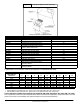
ADJUSTING THERMOSTAT ANTICIPATOR
Set the heat anticipator of the thermostat to the proper value.
Each stage of heat is approximately 0.08 amps per relay. See
instructions provided with the thermostat before making this
adjustment.
Heater Model (kW)
Anticipator Setting
(Approximate Amps)
5, 8, 10 (Single Stage) .08
9, 15 (Two Stage) .16
18, 20, 24, 30 (Three Stage) .24
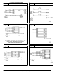
Figure 5 Connection of Transformer
230
C
208
BRN
RED
YEL
BLK
SECONDARY
PRIMARY
A94067
Figure 6 5, 8, 9, and 10 kW Non−fused Heaters